Supercharge Your Innovation With Domain-Expert AI Agents!

Optical thin film and mirror using the same

a technology of optical film and mirror, applied in the field of optical thin film and mirror, can solve the problems of inability to use the lens operation in principle, the difference in the direction of diffusion, and the inability to work in the optical system, so as to enhance the heat resistance increase the heat conductivity of the optical film, and high reflectivity

Inactive Publication Date: 2007-10-23
CANON KK
View PDF36 Cites 6 Cited by
  • Summary
  • Abstract
  • Description
  • Claims
  • Application Information

AI Technical Summary

Benefits of technology

The present invention provides an optical thin film with improved heat resistance. This is achieved by increasing the heat conductivity of the film itself to dissipate and release heat. The optical thin film has a composition with a higher isotope purity than natural abundance ratio. The invention also includes an X-ray mirror made of the optical thin film, which maintains a high reflectivity even through X-ray irradiation. The fine structure of the multilayer film is not broken.

Problems solved by technology

Hence, it is impossible in principle to make use of a lens operation due to its refraction.
In such a case, any general reflector made of a single-layer film has a direct incidence reflectivity of almost 0 and thus is far from functioning in the optical system.
This causes a difference in how diffusion proceeds in the multilayer film, leading to an uneven film.
Therefore, when the multilayer film is heated, its fine structure is broken and changed.
However, in the aforementioned conventional methods of dissipating heat from the multilayer film, heat radiation property of the multilayer film itself is not taken into account.

Method used


Image

  • Optical thin film and mirror using the same
  • Optical thin film and mirror using the same

Examples


example 1

(Example 1)

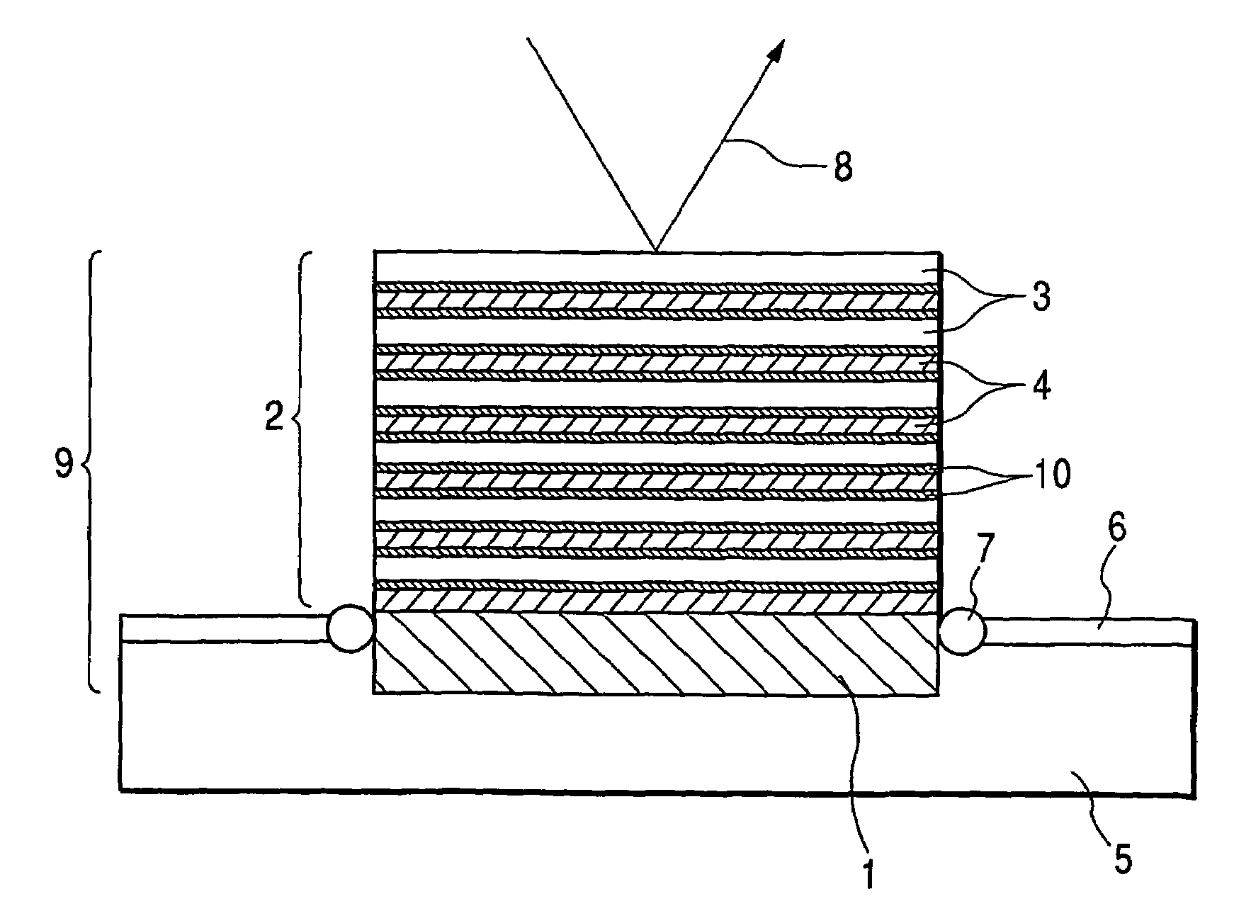
[0020]FIG. 1 is a schematic sectional view of a soft X-ray multilayer film mirror according to the present invention.

[0021]A soft X-ray multilayer film mirror 9 is made up of a multilayer film 2 obtained by alternately stacking an Si layer 3 and an Mo layer 4 on a substrate 1 by magnetron sputtering. A holder 6 holding the multilayer film mirror2 allows a cooling medium 5 such as water to flow therein. Also, the mirror has an O ring 7 that prevents the cooling medium 5 from leaking to the outside of the holder 6. With this arrangement, it is possible to cool the multilayer film 2 that is apt to increase its temperature due to the incidence of a soft X-ray 8.

[0022]The substrate 1 is preferably made of a material of high heat conductivity, for example, Si, Ni, Cu, or Ag.

[0023]When the Si layer 3 was formed on a surface of the substrate 1, sputtering was performed using Si as a target with an isotope purity higher than that in a natural state.

[0024]Similarly to the above, wh...

example 2

(Example 2)

[0033]Next, a soft X-ray multilayer film mirror according to another embodiment of the present invention will be described.

[0034]The soft X-ray multilayer film mirror of this example was made up of the multilayer film 2 obtained by alternately stacking the Si layer 3 and the Mo layer 4 on the substrate 1 having a high heat conductivity by magnetron sputtering as in Example 1. The Mo layer 4 was a layer containing Mo with a natural isotopic abundance ratio and a heat conductivity of 0.34 cal / sec.cm.deg. On the other hand, the Si layer 3 contained 28Si at an abundance of 99% or more with a heat conductivity of about 0.32 cal / sec.cm.deg. This value approximates the heat conductivity of the Mo layer. As discussed above, a substantially uniform heat conductivity was attained throughout the multilayer film, so that the heat inside the multilayer film was able to be easily transferred to the substrate 1. Thus, the heat resistance of the Mo / Si multilayer film was improved to real...

example 3

(Example 3)

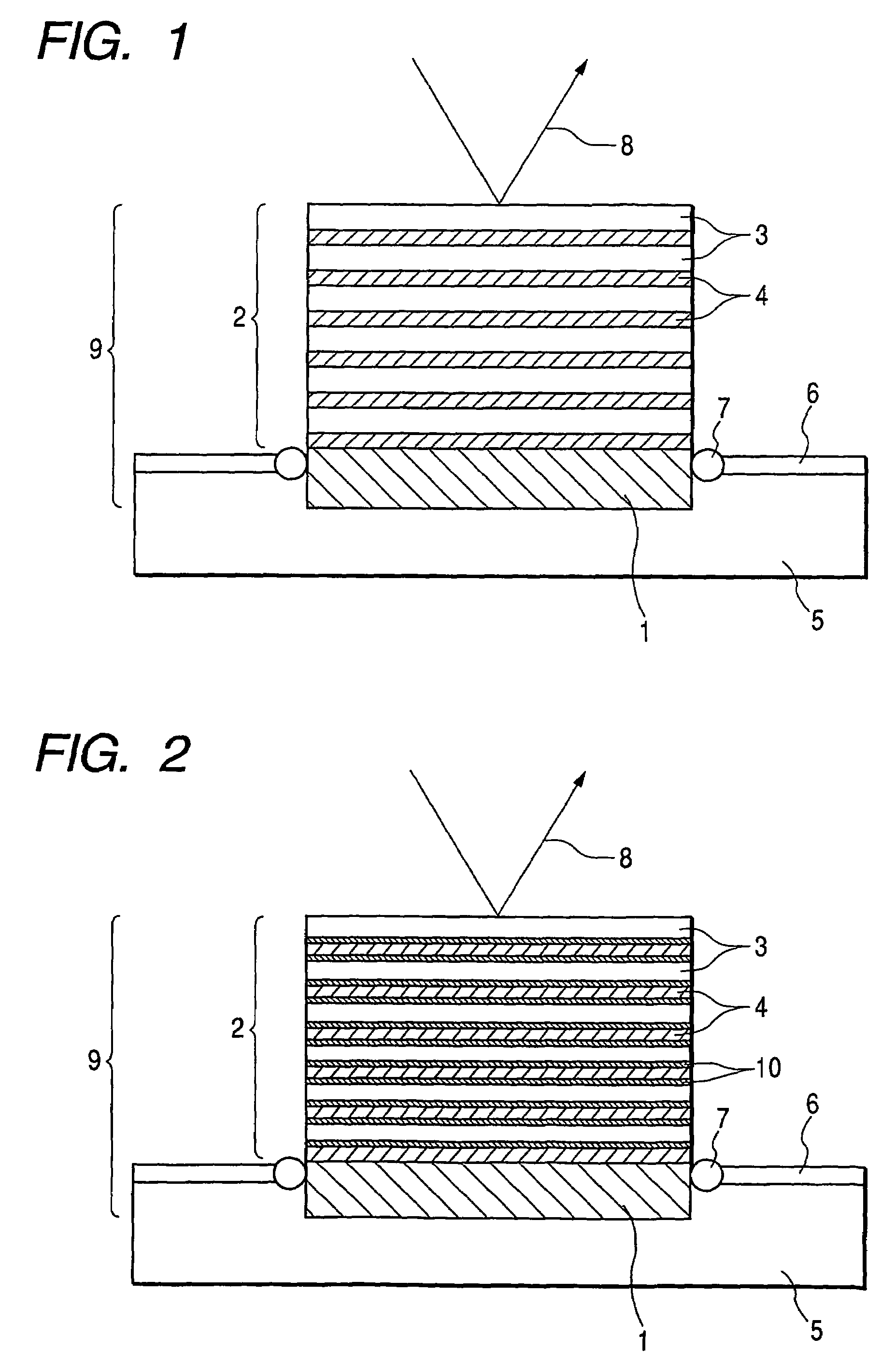
[0035]Next, description will be given of a soft X-ray multilayer film mirror according to still another embodiment of the present invention, referring to FIG. 2.

[0036]The soft X-ray multilayer film mirror of this example was obtained by forming on the substrate 1 having a high heat conductivity, the Si layer 3 and the Mo layer 4, which sandwiched a B4C layer 10 that is an intermediate layer, by magnetron sputtering like Example 1. The multilayer film 2 of a four-layer structure obtained by forming the Si layer 3, the B4C layer 10, the Mo layer 4, and the B4C layer 10 in this order was regarded as a multilayer film in one cycle. The multilayer film 2 was formed by stacking the film of one cycle. According to this method, the Si layer 3 and the Mo layer 4 were unadjacent in the multilayer film, making it possible to prevent the production of interface compounds that would naturally occur between the Si layer 3 and the Mo layer 4.

[0037]An layer containing 28Si at an abundanc...


PUM

PropertyMeasurementUnit
refractive indexaaaaaaaaaa
incident wavelengthaaaaaaaaaa
temperatureaaaaaaaaaa

Abstract

To provide an optical thin film structure capable of efficiently dissipating heat in an optical thin film which is generated upon irradiating a surface of an X-ray mirror made up of the optical thin film with an X-ray. The optical thin film having an isotope purity higher than a natural isotope abundance ratio is formed on a mirror to increase heat conductivity of the optical thin film itself and quickly dissipate heat accumulated in the thin film to the outside of an optical system. Consequently, the mirror having high reflectively can be obtained, in which a fine structure of the optical thin film is by no means broken.

Description

TECHNICAL FIELD[0001]The present invention relates to an optical thin film and a mirror using the same. In particular, the invention relates to a multilayer film mirror used in a soft X-ray region.BACKGROUND ART[0002]In a soft X-ray region, light is significantly absorbed in all substances and in addition, a refractive index approximates 1. Hence, it is impossible in principle to make use of a lens operation due to its refraction. To that end, an optical system is made up of a mirror. In such a case, any general reflector made of a single-layer film has a direct incidence reflectivity of almost 0 and thus is far from functioning in the optical system. In contrast, a multilayer film made of a material relatively low in light absorption can function as a direct incidence mirror optical element, making it possible to use a reflective optical system realized by the utilization of effects thereof.[0003]Heretofore, a reflector has been developed in order to obtain the aforementioned optic...

Claims


Application Information

Patent Timeline
Patent Type & Authority Patents(United States)
IPC IPC(8): G21K1/06C23C14/14G02B5/08G02B5/26G02B5/28
CPCB82Y10/00G02B5/0891G02B5/283G03F7/70958G03F7/70983G21K1/062G03F7/70891G21K2201/065
Inventor IMAI, KYOKOANDO, KENJIKANAZAWA, HIDEHIRO
Owner CANON KK
Features
  • R&D
  • Intellectual Property
  • Life Sciences
  • Materials
  • Tech Scout
  • Unparalleled Data Quality
  • Higher Quality Content
  • 60% Fewer Hallucinations
Learn More