
Bis-chelating ligand and use thereof in carbonylation processes

a carbonylation process and ligand technology, applied in the direction of organic compound catalysts, physical/chemical process catalysts, chemical compound catalysts/hydrides/coordination complexes, etc., can solve the problem that many of the ligands disclosed in the art cannot be easily fine-tuned to provide high selectivity, and the activity of metal-ligand complex catalysts disclosed in these carbonylation processes is undetectable or insufficient stability, etc. problems, to achieve the effect o

Active Publication Date: 2007-11-13
DOW TECH INVESTMENTS
View PDF30 Cites 7 Cited by
  • Summary
  • Abstract
  • Description
  • Claims
  • Application Information

AI Technical Summary

Benefits of technology

This patent describes a new type of chemical compound that can be used as a catalyst in chemical reactions. This compound is made up of a specific formula that allows for the bonding of a transition metal to a ligand. This new catalyst is more effective and selective than previous catalysts, particularly in hydroformylation processes. The patent also describes a process for using this new catalyst to produce useful organic compounds. Overall, this patent provides a new and improved tool for chemical research and development.

Problems solved by technology

Disadvantageously, many of the transition metal-ligand complex catalysts disclosed for these carbonylation processes exhibit undesirably low activity or insufficient stability.
More disadvantageously, many of the disclosed transition metal-ligand complex catalysts exhibit high isomerization selectivity of long chain alpha-olefins to internal olefins.
Even more disadvantageously, many of the ligands disclosed in the art cannot be easily fine-tuned to provide high selectivity to the desired hydroformylation product.

Method used


Image

  • Bis-chelating ligand and use thereof in carbonylation processes
  • Bis-chelating ligand and use thereof in carbonylation processes
  • Bis-chelating ligand and use thereof in carbonylation processes

Examples


example 1

Synthesis of Ligand A

[0056]The following procedure was used to prepared Ligand A having the formula:

[0057]

At the start, a precursor compound designated “TMS-TMS-PCl2” was prepared having the formula:

[0058]

in accordance with the following procedure.

[0059]To a cold (−30° C.) solution of tetrahydrofuran (20 ml) and 3,3′-bis(trimethylsilyl)-5,5′-di-t-butyl-2,2′-biphenol (TMS-diol, 6.00 g, 13.6 mmol) was added with stirring triethylamine (2.80 g, 27.7 mmol) and phosphorus trichloride (PCl3) (0.933 g, 6.80 mmol). A white precipitate formed immediately, and the slurry was stirred and refluxed for 4 hours. The resulting amine chloride salt was filtered off and washed with tetrahydrofuran. The filtrate was cooled to −30° C. To this cold solution was added PCl3 (1.50 g, 10.9 mmol) and triethylamine (1.4 g, 13.9 mmol) with stirring. A white precipitate formed immediately. The mixture was stirred for 2 hours at room temperature and then filtered to remove the amine salt. The filtrate was evapor...

example 2

Synthesis of Ligand D

[0061]The following procedure was followed to prepare Ligand D having the formula:

[0062]

[0063]At the start, a precursor compound designated “TB-MesTMS-PCl2” was prepared having the formula:

[0064]

in accordance with the following procedure:

[0065]3,3′-Di-t-butyl-1,1′-biphenyl phosphorochloridite (TB-PCl) was prepared according to a procedure described in U.S. Pat. No. 4,748,261. To a cold (−30° C.) solution containing tetrahydrofuran (10.0 ml) and TB-PCl (1.508 g, 4.134 mmol) was added with stirring a cold (−30° C.) solution containing tetrahydrofuran (10.0 ml) and 3,3′-bis(trimethylsilyl)-5,5′-bis(2,4,6-trimethylphenyl)-2,2′-biphenol (MesTMS-diol) (2.344 g, 4.134 mmol) and triethylamine (0.418 g, 4.134 mmol). After stirring the reaction mixture for 1 hour at room temperature, triethylamine (0.6312 g, 6.25 mmol) was added to the reaction mixture. After cooling the mixture to −30° C., PCl3 (0.8521 g, 6.205 mmol) in tetrahydrofuran (5.0 ml) was added. The reaction mi...

example 3

Synthesis of Ligand E

[0067]Ligand E having the following formula was prepared as follows.

[0068]

At the start, a precursor compound designated “o-PhB-TMS-PCl2” was prepared having the formula.

[0069]

To a cold (−30° C.) solution containing tetrahydrofuran (THF) (40 ml), diethyl ether (80 ml), 3,3′-diphenyl-5,5′-di-t-butyl-2,2′-biphenol (2.9093 g, 6.456 mmol), and N,N-dimethylaniline (1.6434 g, 13.561 mmol) was added with stirring a cold (−30° C.) solution containing diethyl ether (10 ml) and PCl3 (0.9312 g, 6.781 mmol). After stirring the mixture for one hour at ambient temperature, an N,N-dimethylaniline hydrochloride salt was filtered and washed with ether. The filtrate was evaporated under vacuum to yield a white solid, which was triturated in acetonitrile (15 ml) for 2 hours, filtered and dried. Yield of 3,3′-diphenyl-5,5′-di-t-butyl-2,2′-biphenyl phosphorochloridite (oPhB-PCl): 2.89 g, 87%. 31P NMR (122 MHz, CDCl3, δ): 176.80 ppm.

[0070]To a cold (−30° C.) solution of tetrahydrofura...


PUM

PropertyMeasurementUnit
total pressureaaaaaaaaaa
temperatureaaaaaaaaaa

Abstract

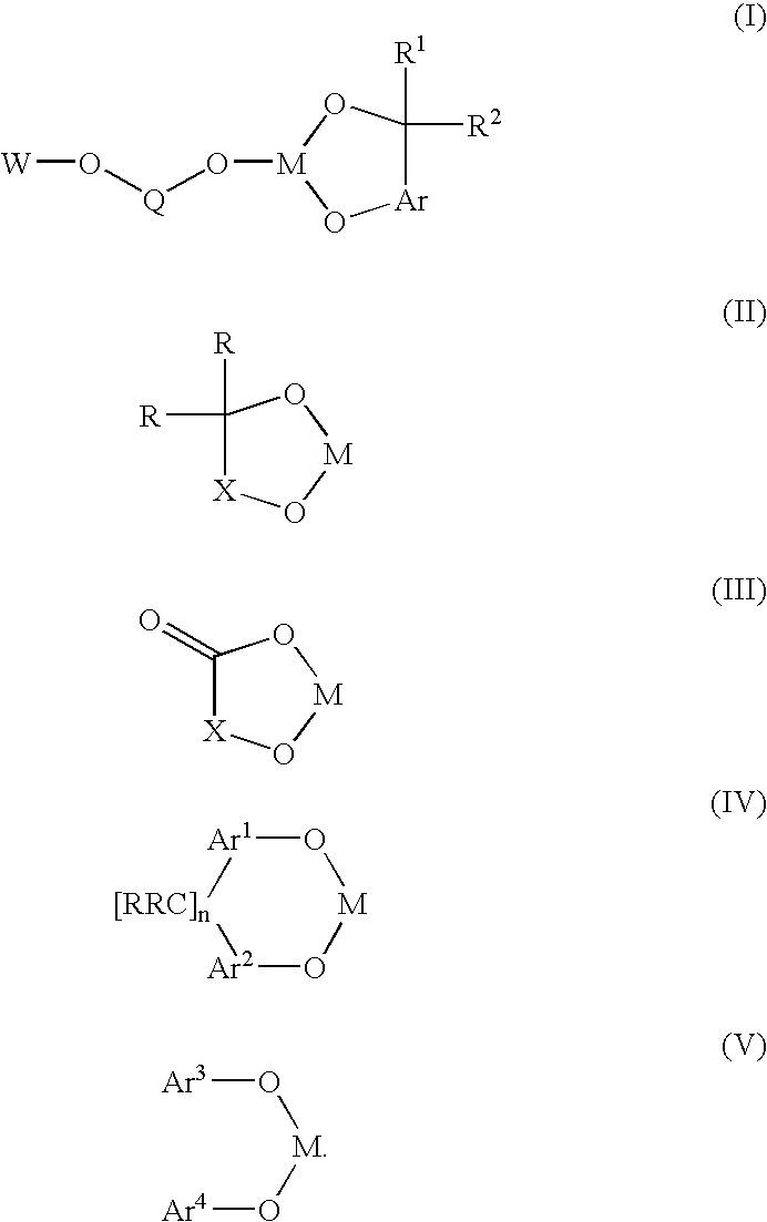
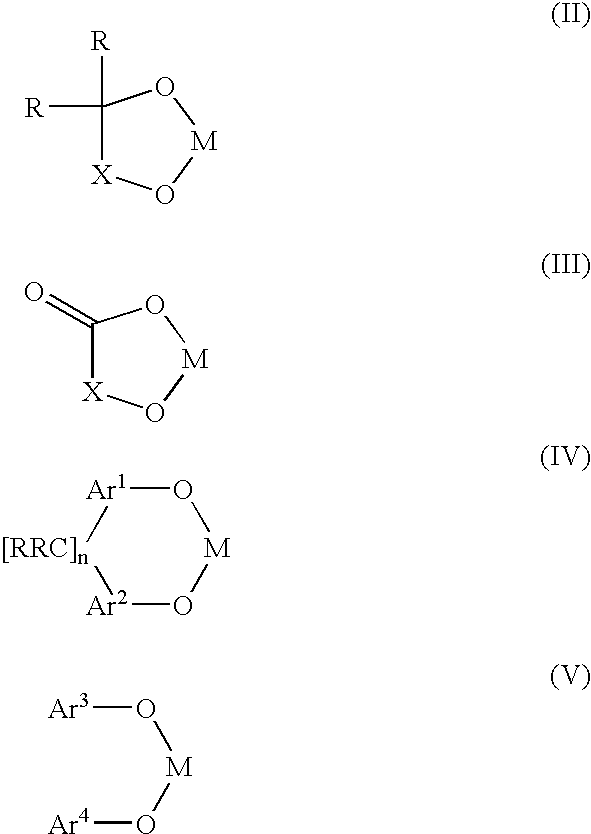
A novel bis-chelating composition characterized by formula I: wherein M is a Group VB element; R1 and R2 are each independently selected from hydrogen and monovalent hydrocarbyl radicals; or R1 and R2 are bonded together to form a diradical; or one of R1 or R2 is hydrogen or a monovalent hydrocarbyl radical, while the other of R1 or R2 is a hydrocarbyl radical bonded to an atom in Ar; wherein Ar is selected from 1,2-arylenes; Q is selected from 1,2-arylenes, 2,2′-bisarylenes and alkyl diradicals; and W is selected from II, III, IV, or V: wherein M is as defined hereinbefore; each R is independently selected from hydrogen and monovalent hydrocarbyl radicals; X is selected from alkyl and aryl diradicals; Ar1 and Ar2 are each independently selected from 1,2-arylenes;Ar3 and Ar4 are each independently selected from monovalent aryl radicals; and n in formula IV is 0 or 1. The composition finds utility as a ligand in catalysts for carbonylation processes

Description

CROSS REFERENCE TO RELATED APPLICATION[0001]This patent application claims the benefit of U.S. provisional application Ser. No. 60 / 418,620, filed on Oct. 15, 2002.BACKGROUND OF THE INVENTION[0002]This invention relates to a bis-chelating ligand composition, particularly of Group VB elements (P, As, Sb), and its use in transition metal complex catalyzed reactions. Preferably, this invention relates to a bis-chelating ligand composition, particularly of Group VB elements, and its use in transition metal-ligand complex catalyzed carbonylation processes, preferably, hydroformylation processes.[0003]Carbonylation processes directed to the production of oxygenated products are well known and generally involve reaction of an organic compound with carbon monoxide and often a third reactant, preferably, hydrogen. See, for example, J. Falbe, “New Syntheses With Carbon Monoxide,” Springer Verlag, New York, 1980. Such processes may include the carbonylation of organic compounds, such as olefins...

Claims


Application Information

Patent Timeline
Patent Type & Authority Patents(United States)
IPC IPC(8): C07F15/00B01J31/00C07F9/02B01J31/16B01J31/18C07C45/50C07F9/6574
CPCB01J31/1608B01J31/185C07F15/008C07C45/50C07F9/65746C07C47/42B01J2231/321B01J2531/80B01J2531/821B01J2531/822B01J2531/827B01J2531/845
Inventor PENG, WEI-JUNHOLLADAY, JOHNATHAN E
Owner DOW TECH INVESTMENTS
Learn More