Fine pitch electrical interconnect assembly

a technology of electrical interconnection and assembly, which is applied in the direction of coupling contact members, coupling device connections, securing/insulating coupling contact members, etc., can solve the problems of stressing components, soldering these connectors to printed circuit boards, and increasing scrutiny of tin lead alloy solder and associated chemicals

Inactive Publication Date: 2008-02-05
R&D SOCKETS INC
View PDF137 Cites 74 Cited by
  • Summary
  • Abstract
  • Description
  • Claims
  • Application Information

AI Technical Summary

Benefits of technology

[0003]The current trend in connector design for those connectors utilized in the computer field is to provide both high density and high reliability connectors between various circuit devices. High reliability for such connections is essential due to potential system failure caused by improper connections of devices. Further, to assure effective repair, upgrade, testing and / or replacement of various components, such as connectors, cards, chips, boards, and modules, it is highly desirable that such connections be separable and reconnectable in the final product.

Problems solved by technology

High reliability for such connections is essential due to potential system failure caused by improper connections of devices.
The tin lead alloy solder and associated chemicals used throughout the process of soldering these connectors to the printed circuit board have come under increased scrutiny due to their environmental impact.
The plastic housings of these connectors undergo a significant amount of thermal activity during the soldering process, which stresses the component and threatens reliability.
The soldered contacts on the connector body are typically the mechanical support for the device being interfaced by the connector and are subject to fatigue, stress deformation, solder bridging, and co-planarity errors, potentially causing premature failure or loss of continuity.
In particular, as the mating connector or semiconductor device is inserted and removed from the connector attached to the printed circuit board, the elastic limit on the contacts soldered to the circuit board may be exceeded causing a loss of continuity.
These connectors are typically not reliable for more than a few insertions and removals of devices.
These devices also have a relatively long electrical length that can degrade system performance, especially for high frequency or low power components.
The pitch or separation between adjacent device leads that can be produced using these connectors is also limited due to the risk of shorting.
Such bonding, however, does not lend itself readily to high-density connections because of possible wire breakage and accompanying mechanical difficulties in wire handling.
While this technique has proven successful in providing high-density interconnections for various structures, this technique does not allow facile separation and subsequent reconnection of the circuit members.
Such elastomeric connectors require a relatively high force per contact to achieve adequate electrical connection, exacerbating non-planarity between mating surfaces.
Location of the conductive elements is generally not controllable.
The interconnection with the circuit elements can be sensitive to dust, debris, oxidation, temperature fluctuations, vibration, and other environmental elements that may adversely affect the connection.

Method used


Image

  • Fine pitch electrical interconnect assembly
  • Fine pitch electrical interconnect assembly
  • Fine pitch electrical interconnect assembly

Examples


Embodiment Construction

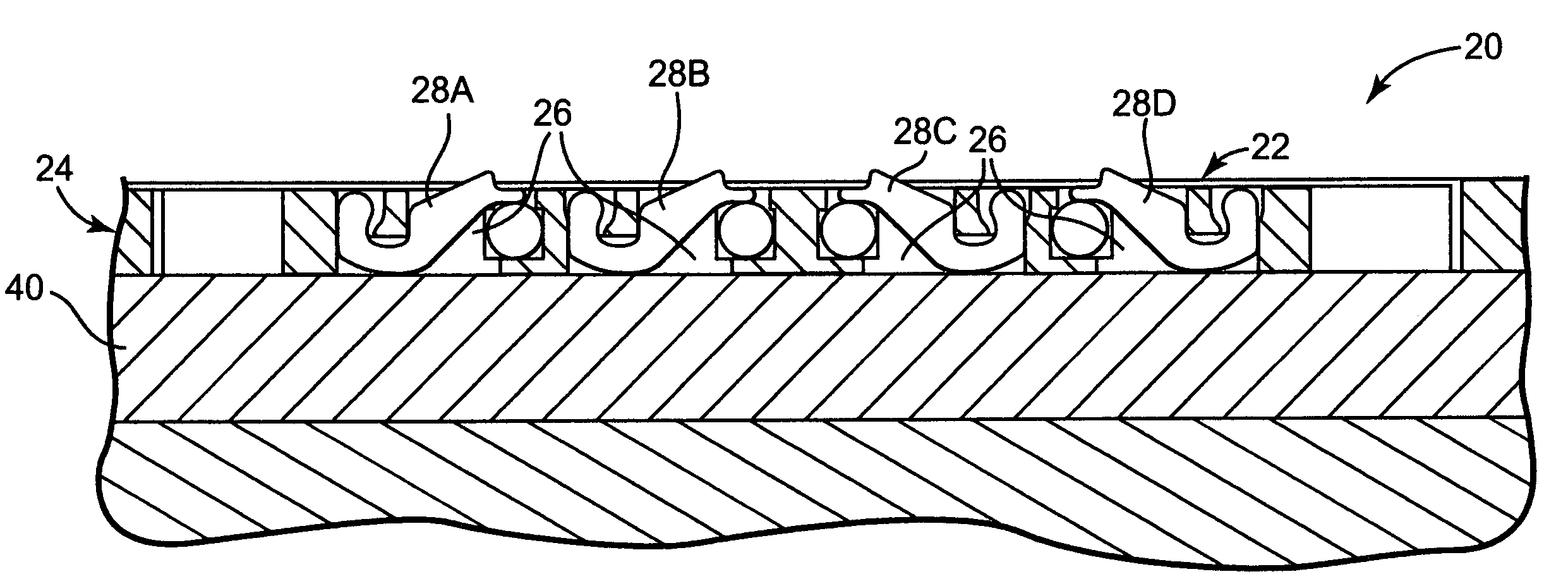
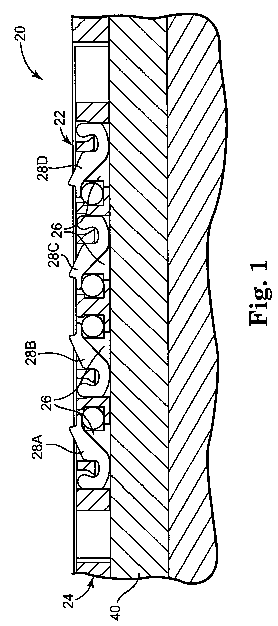
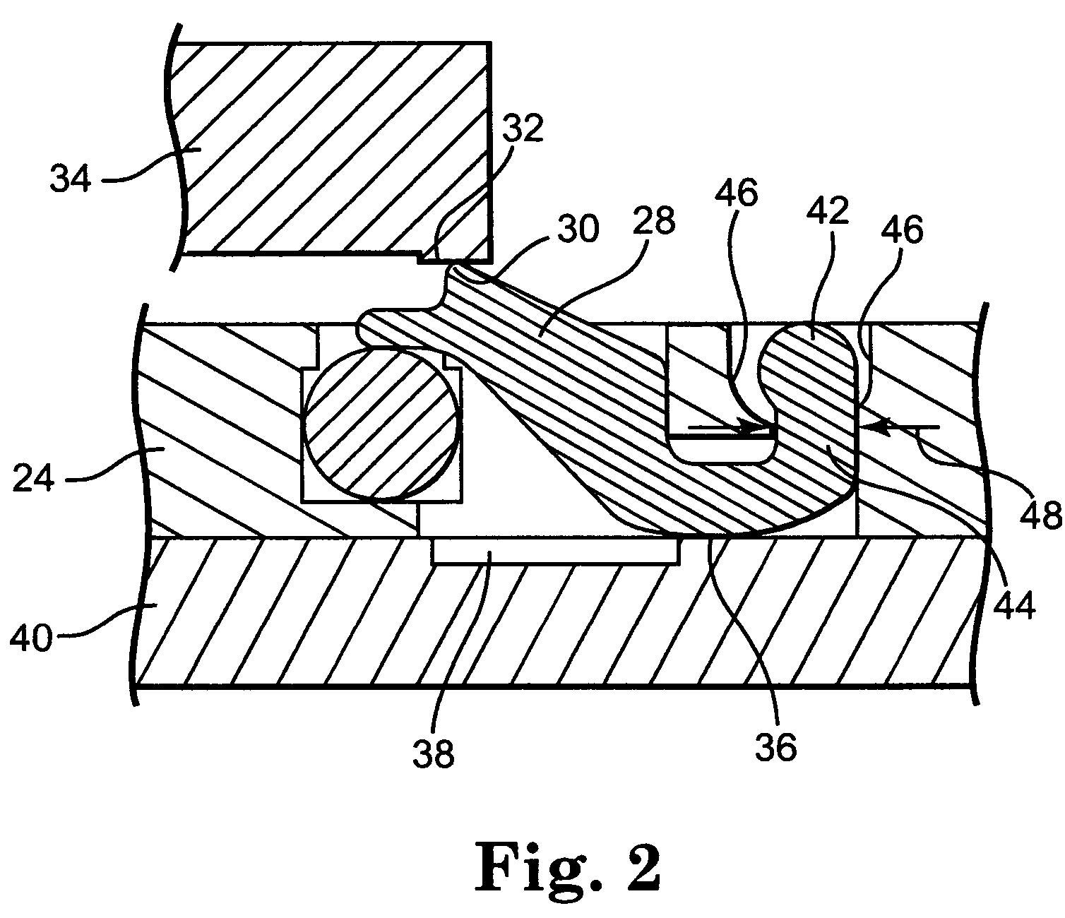
[0052]The present invention is directed to a technique for creating an insulator housing in low, medium, or high volume by laminating layers of precisely patterned materials. The patterned layers can be constructed from the same or multiple material types. The layers are optionally selectively laminated to relieve stress caused by thermal expansion differentials.

[0053]The present construction method permits internal features that would normally be impossible to mold or machine. For large pin count devices, the laminating process produces an inherently flat part without requiring molds. Stiffening layers made of materials such as BeCu, Cu, ceramic, or polymer filled ceramic can be added to provide additional strength and to provide thermal stability during solder reflow.

[0054]The multi-layered housing can also include circuitry layers. Power, grounding and / or decoupling capacitance can be added between layers or between pins, and unique features such as embedded IC devices or RF ante...


PUM


Abstract

An electrical interconnect assembly for electrically interconnecting terminals on a first circuit member with terminals on a second circuit member. The electrical interconnect assembly includes a housing having a plurality of through openings extending between a first surface and a second surface. A plurality of electrical contact member are positioned in a plurality of the through openings. The contact members have at least one engagement feature forming a snap-fit relationship with the housing. A stabilizing structure on the housing limits deflection of the contact members in at least one direction.

Description

[0001]The present application claims the benefit of U.S. Provisional Patent application Ser. No. 60 / 487,630, entitled Snap-in Retention Contact System, filed Jul. 16, 2003, and a continuation-in-part of PCT / US2004 / 022886 entitled Electrical Interconnect Assembly with Interlocking Contact System, filed Jul. 15, 2004.FIELD OF THE INVENTION[0002]The present invention is directed to an electrical interconnect assembly with an interlocking contact system for electrically connecting a first circuit members to one or more second circuit members.BACKGROUND OF THE INVENTION[0003]The current trend in connector design for those connectors utilized in the computer field is to provide both high density and high reliability connectors between various circuit devices. High reliability for such connections is essential due to potential system failure caused by improper connections of devices. Further, to assure effective repair, upgrade, testing and / or replacement of various components, such as con...

Claims


Application Information

Patent Timeline
Patent Type & Authority Patents(United States)
IPC IPC(8): H01R12/00H01R12/16H01R13/24H01R24/00
CPCH01R13/2414H01R13/2435H01R23/68H01R12/523H01R13/24H01R13/22
Inventor RATHBURN, JAMES J.CAVEGN, MARTIN
Owner R&D SOCKETS INC
Why Eureka
Try Eureka