Apparatus and methods for ion beam implantation using ribbon and spot beams

a technology of ion beam and spot beam, which is applied in the direction of separation process, particle separator tube details, instruments, etc., can solve the problems of ensuring a ribbon beam and detectable stripes of varying ion beam dose in the workpiece, and achieve satisfactory control, improve processing throughput, and achieve positive control of the uniformity of the current in the beam more difficult

Active Publication Date: 2008-02-05
ADVANCED ION BEAM TECHNOLOGY INC
View PDF2 Cites 66 Cited by
  • Summary
  • Abstract
  • Description
  • Claims
  • Application Information

AI Technical Summary

Benefits of technology

[0016]The second mode is likely to be advantageous when using high-current, low-energy beams (for example greater than 1 mA at energies below 3 keV) under which conditions space-charge and other effects make positive control of the uniformity of the current in a beam more difficult. The first mode requires slower motions and is likely to deliver higher processing throughput at energies where satisfactory control of the ion beam profile can be achieved. The currents in the multipole lens in either mode may be adjusted to fine-tune the beam current density profile of the beam, even though at low energy this control is insufficient to ensure a uniform implant in one pass with a ribbon beam. In the second mode, this may be valuable to approximate a smooth Gaussian beam profile. Without a smooth beam profile, the method of passing the workpiece in regular increments through the ion beam may cause detectable stripes of varying ion beam dose in the workpiece.
[0017]A further aspect of the invention provides a second lens after the first multipole lens, whose function is to collimate the ion beam. This is particularly important for the first operating mode, i.e. the ribbon-beam case, where systematic variation in the implant angle across the face of the workpiece would otherwise occur. It is also of value to reduce the range of angular variation in the ion beam in the second mode.
[0020]1. To generate a ribbon beam for ion implantation which is mass-analyzed efficiently with a single analyzing magnet in a short, relatively simple beamline with high resolving power;
[0021]2. To provide a second operating mode where the beam can be smaller than the target for implantation, and the target is scanned in a 2D pattern to accomplish uniform implantation;
[0023]4. To provide a means of decelerating the ion beam in either implantation mode in a manner which eliminates the usual contamination with high-energy neutral atoms;

Problems solved by technology

In certain circumstances such as when using high-current low energy beams it may not be possible to assure a ribbon beam that is sufficiently uniform.
The currents in the multipole lens in either mode may be adjusted to fine-tune the beam current density profile of the beam, even though at low energy this control is insufficient to ensure a uniform implant in one pass with a ribbon beam.
Without a smooth beam profile, the method of passing the workpiece in regular increments through the ion beam may cause detectable stripes of varying ion beam dose in the workpiece.

Method used


Image

  • Apparatus and methods for ion beam implantation using ribbon and spot beams
  • Apparatus and methods for ion beam implantation using ribbon and spot beams
  • Apparatus and methods for ion beam implantation using ribbon and spot beams

Examples


first embodiment

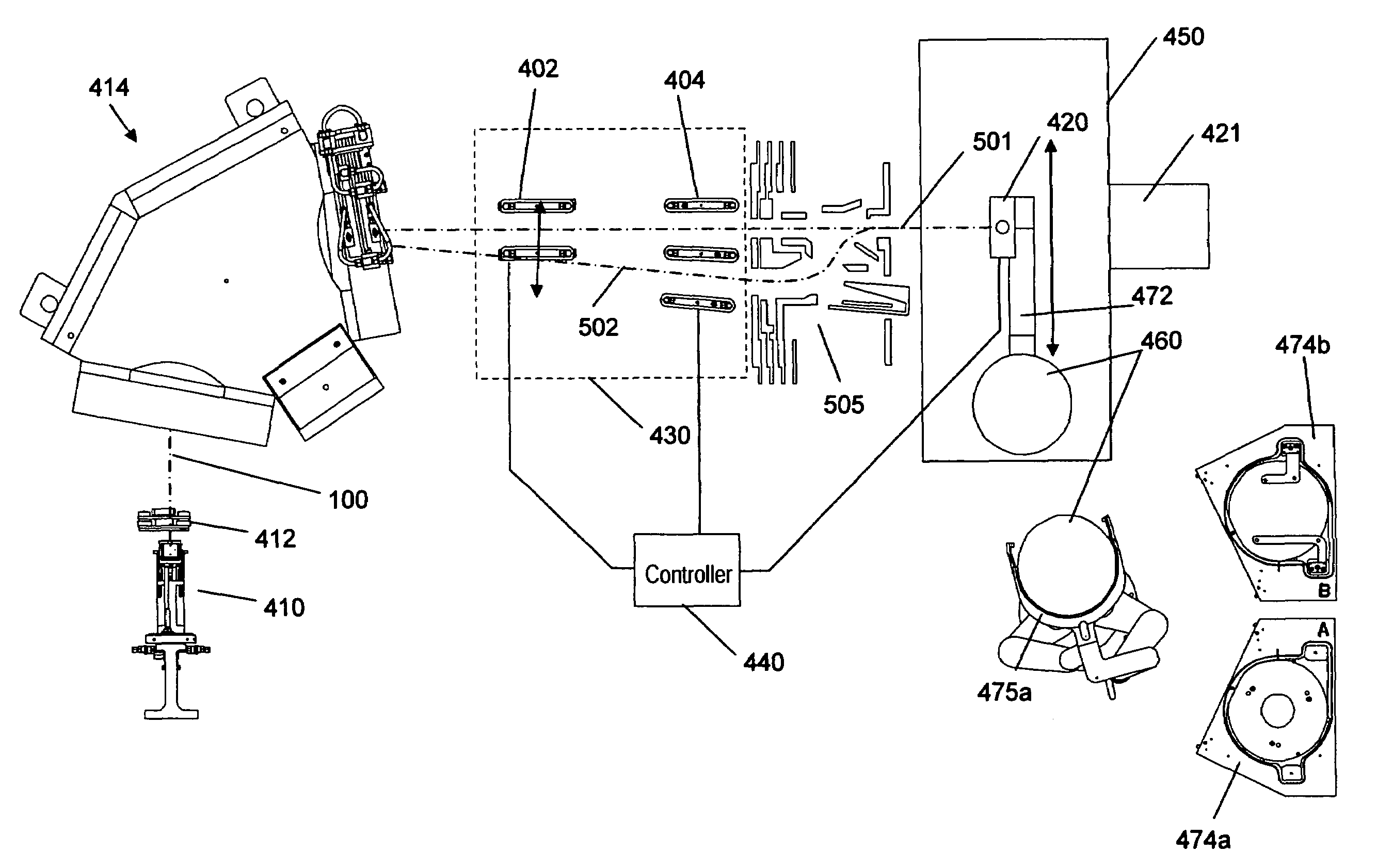
[0039]FIG. 3 is a perspective view of an ion implantation system of the present invention. The system comprises an ion source 102 that produces an ion beam 100 that emanates from a divergent extraction optics similar to those shown in FIG. 2, a mass analyzer magnet 414, and a collimator lens 200 As will be appreciated by those skilled in the art, these elements are housed in a vacuum enclosure (not shown). Magnet 414 comprises upper and lower coils 120, 121 and a yoke 110 with an entrance aperture 164 and an exit aperture 166. The magnet is curved over an arc of about 90°. The cross-section of the ion beam is relatively tall and thin and the longer dimension of the cross-section lies in the non-dispersive plane of magnet 110. The ion beam is slightly divergent upon exiting the extraction electrode; and as the beam travels along the beam path, it continues to become taller as the beam rays continue to diverge such that when it approaches the target (which may be a semiconductor wafer...

second embodiment

[0040]The analyzer magnet in FIG. 3 has a central passageway for the beam that has a top and bottom that are parallel from entrance aperture 164 to exit aperture 166. Thus, a cross-section of the magnet taken along lines A-A of FIG. 3 at any point along the radius of curvature of the magnet is the same. However the ion beam is diverging. In a second embodiment, the construction of the magnet is modified as illustrated by the three cross sections in FIGS. 4a, b, and c so that the height of the beam passage through the magnet increases as the beam expands. In particular, as shown in FIG. 4a, which depicts a cross-section closest to the entrance aperture 164 of the magnet, the height of the central passageway 160 is smallest. As shown in FIG. 4c, which depicts a cross-section closest to the exit aperture 166, the height of the central passageway is largest; and as shown in FIG. 4b which depicts a cross-section between those of FIGS. 4a and 4c, the height is intermediate that of the oth...


PUM


Abstract

This invention discloses an ion implantation apparatus with multiple operating modes. It has an ion source and an ion extraction means for extracting a ribbon-shaped ion beam therefrom. The ion implantation apparatus includes a magnetic analyzer for selecting ions with specific mass-to-charge ratio to pass through a mass slit to project onto a substrate. Multipole lenses are provided to control beam uniformity and collimation. The invention further discloses a two-path beamline in which a second path incorporates a deceleration system incorporating energy filtering. The invention discloses methods of ion implantation in which the mode of implantation may be switched from one-dimensional scanning of the target to two-dimensional scanning, and from a simple path to an s-shaped path with deceleration.

Description

CROSS REFERENCE TO RELATED APPLICATIONS[0001]This application is a continuation-in-part of U.S. patent application Ser. No. 11 / 123,924, filed May 6, 2005, now U.S. Pat. No. 7,112,789 for “High Aspect Ratio, High Mass Resolution Analyzer Magnet and System for Ribbon Ion Beams,” which claims priority to U.S. Provisional Application No. 60 / 571,965, filed May 18, 2004. Each of these applications is incorporated herein by reference in its entirety.FIELD OF THE INVENTION[0002]The invention disclosed herein relates generally to apparatus for performing ion implantation. Specifically, this invention relates to an improved implantation apparatus and methods for performing a high / medium current ion implantation at different ion energies.BACKGROUND OF THE INVENTION[0003]Ion implantation is a ballistic process used to introduce into a target substrate atoms or molecules, generally referred to as dopants, to make materials with useful properties. Of particular interest, ion implantation is a com...

Claims


Application Information

Patent Timeline
Patent Type & Authority Patents(United States)
IPC IPC(8): H01J37/317H01J37/08H01J37/147H01J37/05H01J49/20
CPCH01J37/05H01J37/3171H01J49/30
Inventor CHEN, JIONGWHITE, NICHOLAS R.
Owner ADVANCED ION BEAM TECHNOLOGY INC
Why Eureka
Try Eureka