Multilayer stent

a multi-layer, stent technology, applied in the field of expandable intraluminal vascular devices, can solve the problems of lack of localized therapeutic pharmacological delivery, lack of stents with metallic claddings, and lack of stents with expansion characteristics,

Inactive Publication Date: 2008-02-26
ABBOTT CARDIOVASCULAR
View PDF45 Cites 45 Cited by
  • Summary
  • Abstract
  • Description
  • Claims
  • Application Information

AI Technical Summary

Benefits of technology

[0009]The present invention is directed to a multilayer intracorporeal device, specifically a multilayer or laminate stent that has a metallic substrate and at least one layer of metallic cladding. The cladding is generally joined to the substrate under high pressure resulting in a structure that resists separation or delamination under normal stress. The cladding metal and the base or substrate material form a bond between them during a deep drawing, cold drawing, or co-drawing on a mandrel process. The method of combining two or more layers of different materials allows for the combination of desirable properties of those materials. Typical material properties to be considered for stent design and performance include strength, ductility, and radiopacity. For example, a substrate layer material may be chosen for its strength, a first cladding material chosen for its ductility, and a second cladding material chosen for its radiopacity.

Problems solved by technology

But stents can sometimes cause complications including thrombosis, and neointimal hyperplasia by inducement of smooth muscle cell proliferation at the site of implantation of the stent.
Such stents typically also do not provide for delivery of localized therapeutic pharmacological treatment of a blood vessel at the location being treated with the stent, which can be useful for overcoming such problems.
Despite progress in the art, there is presently no stent available that has a metallic cladding for improved strength reinforcement, expansion characteristics and radiopacity.

Method used


Image

  • Multilayer stent
  • Multilayer stent
  • Multilayer stent

Examples


Embodiment Construction

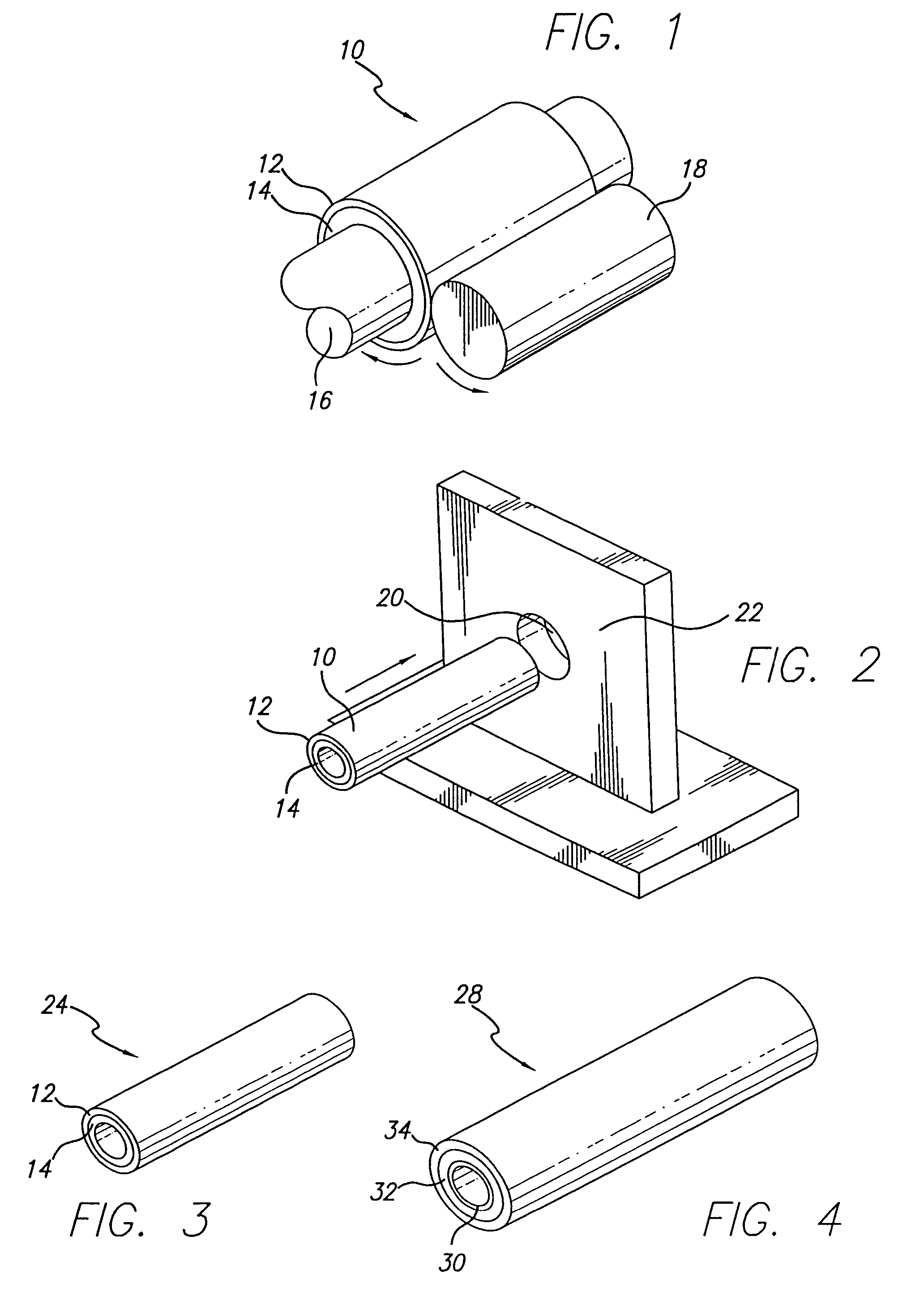
[0023]FIG. 1 is a perspective view of a preferred embodiment of a laminate tube having features of the present invention. As seen in this simplified view, the present invention contemplates creation of laminate tube 10 by joining metal cladding tube 12 to an exterior surface of substrate tube 14. Fundamental to this joining process is first defining the initial diameters of metal cladding tube 12, which should already be in a tubular configuration as seen in FIG. 1, and of substrate tube 14. Tubes 12, 14 can be made by conventional fabrication processes, such as drawing, rolling sheet stock and welding the seam, etc. During these preliminary steps, the diameters and wall thickness of tubes 12 and 14 are selected and set.

[0024]In the preferred embodiment of the present invention, there should be an interference fit between the outside diameter of substrate tube 14 and the inside diameter of metal cladding tube 12. The interference fit prevents unwanted, relative shifting between subs...


PUM

PropertyMeasurementUnit
diameteraaaaaaaaaa
diameteraaaaaaaaaa
diameteraaaaaaaaaa

Abstract

A composite stent having a substrate tube made of stainless steel, a nickel-cobalt-chromium-molybdenum alloy, or chonichrome with at least one metal cladding tube is disclosed. Specifically, the substrate tube is placed within a metal cladding tube made of platinum, gold, tantalum, tungsten, platinum-iridium, palladium, or nickel-titanium, preferably with an interference fit therebetween. The composite, laminate tube then undergoes a series of rolling or cold drawing processes interspersed with heat treating to release built up stresses. When the final diameter of the laminate tube is reached, the cladding has been laminated to the exterior of the substrate tube by a bond generated from the rolling and/or cold drawing operations. The finished laminate tube is then cut by laser cutting or chemical etching to form a suitable stent pattern.

Description

RELATED APPLICATIONS[0001]This is a divisional application of parent application having U.S. Ser. No. 09 / 270,403, filed Mar. 16, 1999, now U.S. Pat. No. 6,620,192 the contents of which are hereby incorporated by reference.BACKGROUND OF THE INVENTION[0002]The present invention relates to expandable intraluminal vascular devices, generally referred to as stents. More precisely, the present invention is directed to stents that have a metallic cladding for improved expansion characteristics and radiopacity.[0003]Stents are used to maintain patency of vessels in the body, such as a patient's arteries. A variety of delivery systems have been devised that facilitate the placement and deployment of stents. The stent is initially manipulated while in its contracted or unexpanded state, wherein its reduced diameter more readily allows it to be introduced into the body lumen, such as a coronary artery, and maneuvered into the target site where a lesion has been dilated. Once at the target site...

Claims


Application Information

Patent Timeline
Patent Type & Authority Patents(United States)
IPC IPC(8): A61F2/06A61F2/90
CPCA61F2/91A61F2/915A61F2230/0013A61F2210/0076A61F2002/91533
Inventor JALISI, MARC M.
Owner ABBOTT CARDIOVASCULAR
Why Eureka
Try Eureka