Optical fiber coupling part

a technology of optical fiber and coupling parts, applied in the field of optical fiber coupling parts, can solve the problems of increasing manufacturing costs, deteriorating mass-productivity, and inability to use the coupling method of a semiconductor laser array and an optical fiber array, and achieve the effect of small coupling system, easy assembly of coupling system, and large operating distance between lens and light-emitting sour

Active Publication Date: 2008-03-18
TOYO SEIKAN GRP HLDG LTD
View PDF20 Cites 41 Cited by
  • Summary
  • Abstract
  • Description
  • Claims
  • Application Information

AI Technical Summary

Benefits of technology

[0013]The optical fiber part of the present invention functions to efficiently send light emitted from a light emitting source to the optical fiber for optical communication, by arranging the end part of the GRIN lens opposed to the light emitting source, and connecting the optical fiber for optical communication to the other end. The GRIN lens, as described above, is the lens using medium materials that are not uniform in refractive index (refractive index becomes larger toward the center of the lens), and functioning as a lens having continuously changing refractive index. FIG. 1 is an explanatory view of the GRIN lens, illustrating a refractive index distribution in a radius direction in the left side, and illustrating its perspective view in the right side. As shown in FIG. 1, the GRIN lens has a 2nd square type refractive index distribution. The numerical aperture NAs of the light emitting source (such as semiconductor laser) is a sine function of a critical angle of a radiation full angle at half maximum, and the numerical aperture NA of the GRIN lens is a sine function of a critical angle of the GRIN lens. The light emitting source having larger numerical aperture spreads the light in a larger area, and the GRIN lens having larger numerical aperture has a higher light-condensing performance.
[0032]According to the optical fiber coupling part with GRIN lens, a coupling profile can be made to have substantially the same thickness as that of the optical fiber, thereby providing a small coupling system in total. Therefore, the semiconductor array and the optical fiber array can be coupled to each other, so that a plurality of semiconductor lasers and a plurality of optical fibers are arranged at short intervals. The operating distance (distance between the lens and the light-emitting source) can be made large, thereby facilitating the assembly of the coupling system without damaging the lens, and the coupling loss can be significantly reduced. In addition, all the optical fiber coupling parts with GRIN lens of the present invention are optical fiber types, and can be formed by using the existing fusion splicing technique as it is, thereby having a significant effect that mass production is realized with easy manufacture.

Problems solved by technology

The method using the lens involves problems in that mutual alignment of the optical axes of the semiconductor laser, the lens, and the optical fiber is complicated, enlarging the entire body of the coupling system at the same time, thereby increasing the manufacturing cost, while relatively high coupling efficiency is obtained.
In addition, since the dimension of the lens is large and a disposition space is thereby largely occupied, this method can not be used for coupling a semiconductor laser array and an optical fiber array in which a plurality of semiconductor lasers and a plurality of optical fibers are arranged at short intervals.
Meanwhile, when making the tip ball optical fiber, a problem is that conventionally the tip part of the fiber is polished around, and therefore mass-productivity is deteriorated and it takes significant labor hours to produce.
Another problem is that, since the tip of the optical fiber is spherical, coupling efficiency is deteriorated due to spherical aberrations.
Thus, such a lens can not sufficiently take in lights emitted from the semiconductor laser for optical communication, whose standard radiation full angle at half maximum θ is approximately 25°, thereby increasing the coupling loss.
However, in this case, it is difficult to align the optical axis, thereby increasing the assembly cost.
However, the problems are that mass-productivity is deteriorated and it takes significant labor to produce, thereby increasing the manufacturing cost.
Further, the GRIN lens is conventionally made of a multi-component glass, and its softening point is about 500 to 600° C. Therefore, such a GRIN lens can not be fusion-spliced with the optical fiber, which is mainly composed of quartz glass.
Thus, an optical adhesive is used, thereby posing problems in that it is difficult to align the optical axis, and an optical characteristic is deteriorated by a change in the quality of the adhesive caused by temperature-raise, when the adhesive absorbs the light and high intensity light thereby enters.
However, in this case, the critical angle of the GI optical fiber is made small, set to be 20° C. or less, (light-condensing performance is small), and therefore it is difficult to sufficiently take in the light emitted from the semiconductor lens for optical communication, whose standard radiation full angle at half maximum 0 is approximately 25°, and therefore the coupling loss is large, and handling property is low when actually assembled as a lens.
However, in this case, the coupling loss of about 3-4 dB must be expected.
Particularly, the problem is that, when the critical angle of the semiconductor laser (sine function of this critical angle=numerical aperture called NAs) is larger than the critical angle of the optical fiber (sine function of this critical angle=numerical aperture called NAf), the light deviates from the core of the optical fiber depending on the emission angle of the light beam, or even if the light reaches the core, the incident angle to the core is equal to the critical angle or larger, thereby failing with regard to entering the single mode optical fiber and deteriorating the coupling efficiency.
In addition, the tip is formed in semi-spherical shape with low yield ratio at a high cost.
Therefore, a disadvantage is that when constructing a coupling system of coupling the optical fiber with semi-spherical lens and the semiconductor laser, the semiconductor laser and the semi-spherical lens collide with each other, resulting in being unusable.
However, a conventional technique relating to the optical fiber with lens can not simultaneously satisfy requirements such as realizing more reduced coupling loss, further facilitating aligning of the optical axes of a semiconductor laser, a lens, and an optical fiber, while maintaining a long operating distance.

Method used


Image

  • Optical fiber coupling part
  • Optical fiber coupling part
  • Optical fiber coupling part

Examples


embodiment 1

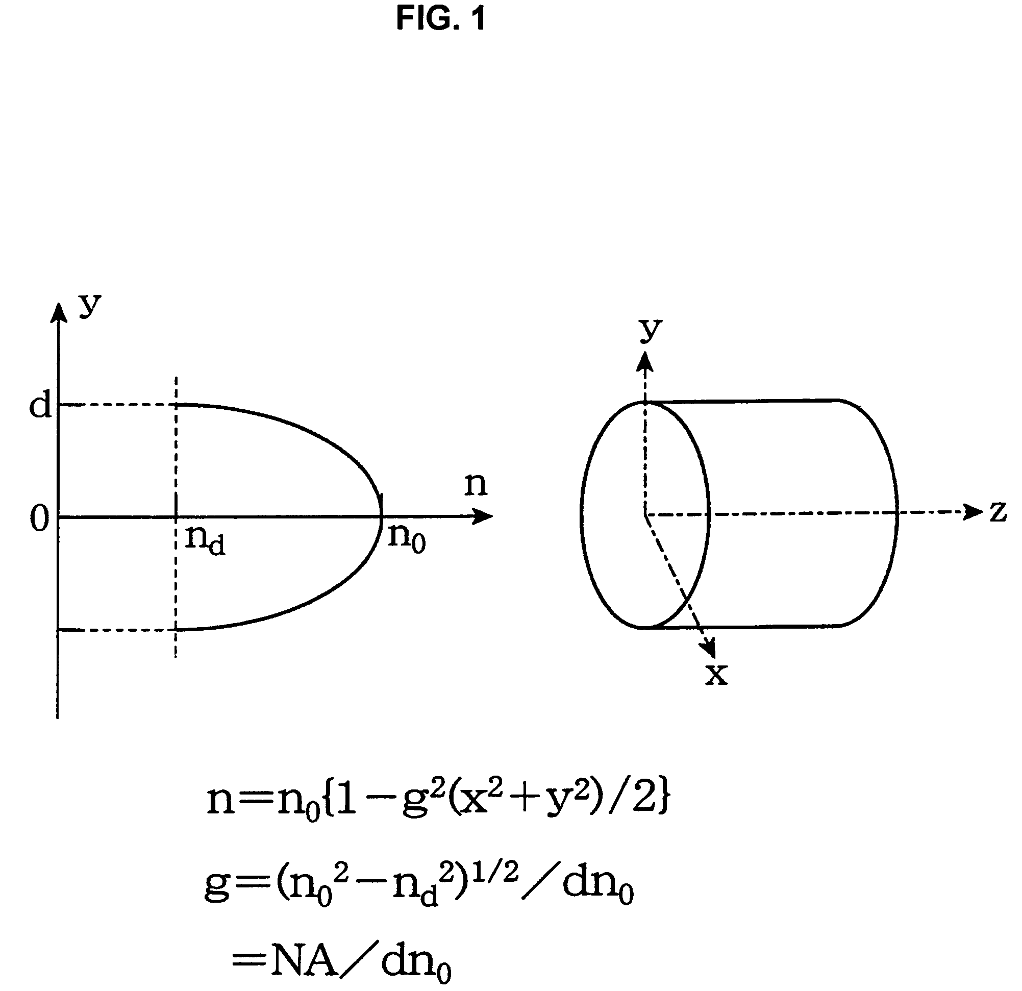
[0046]2 normal hydrochloric acid 9.2 ml was added into a mixture of 75.5 ml silicon tetramethoxide and 183.4 ml isopropanol, and after stirring for 30 minutes, 9.8 ml titanium tetra-n-butoxide was added. Thereafter, 0.01 normal ammonia water was added, and stirred, to obtain a wet gel. After aging the wet gel at a temperature of 50° C. for two days, the wet gel is immersed in 6 normal hydrochloric acid for two hours, so that titanium on an outer periphery is eluted, and concentration distribution of titanium was imparted in the gel. After being immersed, the wet gel is dried at a temperature of 70° C., to obtain a dry gel having about 10 mm diameter. The dry gel thus obtained was subjected to temperature-raise from room temperature to 800° C. at a rate of 150° C. / hr in an oxygen atmosphere, and thereafter to 1250° C. at a rate of 50° C. / hr in a helium atmosphere, and then subjected to baking to obtain a transparent glass body. The refractive index distribution of the columnar glass ...

embodiment 2

[0050]First, in the same process as the first embodiment, after forming the preform of the second GRIN lens having numerical aperture satisfying NA=0.16, the preform was formed into the second GRIN lens-like optical fiber having 150 μm outer diameter by spinning in the electric furnace of the carbon heater.

[0051]Next, after 2 normal hydrochloric acid 9.2 ml was added into a mixture of 76.6 ml silicon tetramethoxide and 184.3 ml isopropanol, 50 ml superfine particulate silica was added to mix therewith, and the mixture thus obtained was stirred for 1 hour and partially hydrolyzed. Then, the solution was divided equally into eight parts, and added with titanium tetra-n-butoxide of concentration as shown in Table 1, to make eight kinds of sol from first layer to eighth layer with different titanium components at regular intervals. Thereafter, 0.01 normal ammonia water was added at regular intervals to adjust the sol.

[0052]First, the sol of the first layer was contained in a polypropyle...

embodiment 3

[0057]First, in the same process as the first embodiment, after forming the preform of the second GRIN lens having numerical aperture satisfying NA=0.16 was formed, the preform was formed into the second GRIN lens-like optical fiber having 150 μm outer diameter by spinning in the electric furnace of the carbon heater.

[0058]Subsequently, tantalum ethoxide was added to and mixed with 1.1 g silicon tetramethoxide by an amount of eight kinds shown in table 2, and 1.3 cc methanol was further added and mixed therein, and the mixture thus obtained was stirred. Thereafter, 0.3 g superfine particulate silica was mixed therein, and after stirring for one hour, 1.3 cc methanol and 0.3 cc pure water were mixed and delivered by drops therein to adjust the sol.

[0059]First, the sol of the first layer was contained in the cylindrical polypropylene vessel having 50 mm inner diameter, and the sol thus contained was rotated at a speed of 1000 revolutions per one minute for 30 minutes to form a cylindr...


PUM


Abstract

An optical fiber coupling part capable of reducing coupling loss while maintaining a large operating distance, and having a good module assembling property. AT least one GRIN lens having numerical aperture NA that is larger than numerical aperture NAs of a light-emitting source (such as a semiconductor laser) is fusion-spliced with one end of the optical fiber. All lights emitted from the light-emitting source can enter the GRIN lens, and the loss of the light can thereby be reduced. In addition, a second GRIN lens having numerical aperture NA2 is fusion-spliced with one end of the optical fiber having numerical aperture NAf, and further a first GRIN lens having numerical aperture NA1, which is larger than numerical aperture NA2, is fusion-spliced with the other end of the second GRIN lens. Thereby, the light emitted from the light-emitting source can efficiently enter the optical fiber, and loss of the light can thereby be reduced. In this case, the formula expressed by NAf≦NA2<NAs≦NA1 is desirable.

Description

BACKGROUND OF THE INVENTION[0001]1. Field of the Invention[0002]The present invention relates to an optical fiber coupling part for coupling a light emitting source such as a semiconductor laser used for optical communication and an optical fiber with high coupling efficiency.[0003]2. Description of the Related Art[0004]A technique for coupling a semiconductor laser and an optical fiber with high coupling efficiency is one of the most important techniques in optical communication. For example, conventional methods of coupling the semiconductor laser and the optical fiber include a method using a lens such as a spherical lens and an aspherical lens, or a method using a tip ball fiber whose tip part is spherical (see U.S. Pat. No. 3,910,677). The method using the lens involves problems in that mutual alignment of the optical axes of the semiconductor laser, the lens, and the optical fiber is complicated, enlarging the entire body of the coupling system at the same time, thereby increa...

Claims


Application Information

Patent Timeline
Patent Type & Authority Patents(United States)
IPC IPC(8): G02B6/32G02B6/02G02B6/255G02B6/42
CPCG02B6/32G02B6/4206G02B6/2551G02B6/42G02B6/255
Inventor MATSUMURA, HIROYOSHISUZUKI, TARO
Owner TOYO SEIKAN GRP HLDG LTD
Why Eureka
Try Eureka