
Processing method of polymer crystal, processing system of polymer crystal, and observation system of polymer crystal

a processing system and polymer crystal technology, applied in the field of macromolecular crystal working methods, can solve the problems of inconvenient laser working by continuous light, infrared laser and visible light laser,

Active Publication Date: 2008-04-08
NIKON CORP +6
View PDF9 Cites 10 Cited by
  • Summary
  • Abstract
  • Description
  • Claims
  • Application Information

AI Technical Summary

Benefits of technology

The present invention provides a method and apparatus for safely and securely working on macromolecular crystals using a pulsed laser. The method uses a short-pulse laser that has high photon energy, allowing for precise working without causing damage to the crystal. The laser light is focused on the crystal, so there is no need for mechanical contact or continuous laser light. The method can be used on a variety of macromolecular crystals, including resins, proteins, sugars, lipids, and nucleic acids. The laser light is also used to strip the crystal from its adhering substance without causing damage or damage to the surrounding area. The invention provides a simple and effective solution for working on macromolecular crystals.

Problems solved by technology

Accordingly, in the case of macromolecular crystals in which thermal deformation must be avoided, working by means of such infrared lasers and visible-light lasers, and laser working by means of continuous light, are unsuitable.

Method used


Image

  • Processing method of polymer crystal, processing system of polymer crystal, and observation system of polymer crystal
  • Processing method of polymer crystal, processing system of polymer crystal, and observation system of polymer crystal
  • Processing method of polymer crystal, processing system of polymer crystal, and observation system of polymer crystal

Examples


embodiment 1

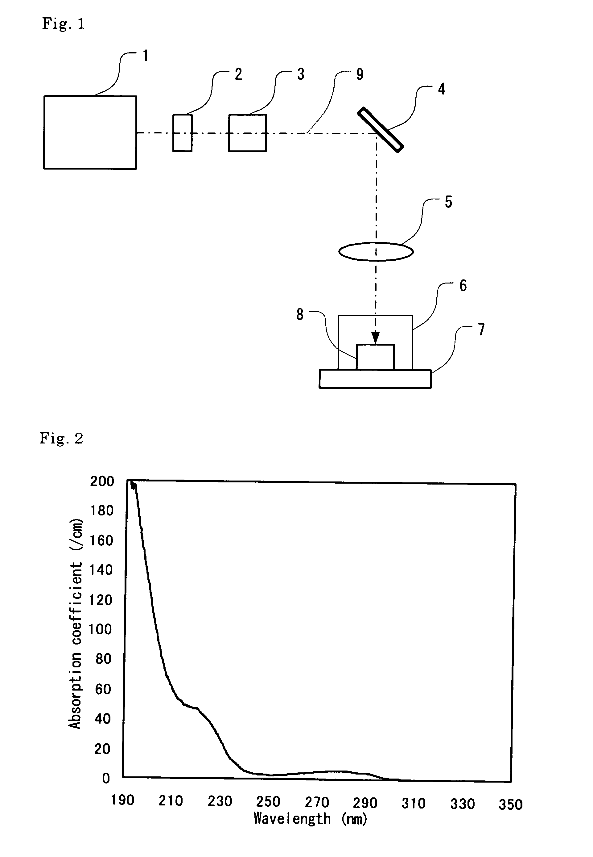
[0122]In order to investigate the basic characteristics of the working method of the present invention, a protein single crystal was irradiated with ultraviolet short-pulse laser light having a wavelength of 193 nm using an apparatus of the type shown in FIG. 1; as a result, the crystal was cut in two. The X-ray diffraction pattern of the crystal following cutting was measured, and a structural analysis was performed.

[0123]A hen-egg white lysozyme protein was selected as the model macromolecule, and a single crystal of this protein was grown in a sample container by the vapor diffusion method. The crystal growth solution used was as follows: namely, a 25 mg / ml solution of the hen-egg white lysozyme sample (re-purified 6 times) was prepared, and this was mixed at a 1:1 ratio with a solution adjusted so that sodium chloride was present at a concentration of 60 mg / ml in a 0.1 M acetic acid buffer solution adjusted to a PH of 4.5; 10 μl of the resulting solution was used. 400 μl of a so...

embodiment 2

[0132]Hole boring working was performed using the same apparatus as that described in Embodiment 1, so that a rectangular cavity was formed in the central portion of the crystal. The hen-egg white lysozyme was selected as the model macromolecule, and a single crystal of this protein constituting the object of working was grown in a sample container using the same growth method and growth conditions as in Embodiment 1. Subsequently, the protein solution in which the crystal was present was removed in the same manner as in Embodiment 1, and the sample container 6 was tightly sealed in a state in which liquid droplets of the external solution were left. A photograph of the crystal prior to laser light irradiation is shown in FIG. 12. The size of the crystal was 0.4 mm×0.6 mm×0.3 mm. The sample container 6 was placed on a stage 7 capable of triaxial movement along the X, Y and Z axes, and the sample was irradiated with ultraviolet short-pulse laser light having a wavelength of 193 nm fr...

embodiment 3

[0136]Using the same apparatus as that used in Embodiment 1, cutting working was performed by irradiating a protein polycrystal with ultraviolet short-pulse laser light having a wavelength of 193 nm, so that a single crystal portion was separated from the polycrystal.

[0137]The growth conditions of the hen-egg white lysozyme polycrystal constituting the material being worked were also the same as in Embodiment 1 and Embodiment 2. FIG. 13(a) shows a photograph of the crystal prior to irradiation with ultraviolet short-pulse laser light. The macromolecular crystal 8 was not an ideal single crystal, but had the form of a polycrystal in which two single crystals (a single crystal appearing as a dark crystal in the center, and a long slender hexagonal crystal appearing to overlap on the right side of the first crystal) were conjoined.

[0138]The spot position on the crystal was varied by causing the stage 7 to perform a linear reciprocating operation at a movement speed of 0.5 mm / sec and a ...


PUM

PropertyMeasurementUnit
wavelengthaaaaaaaaaa

Abstract

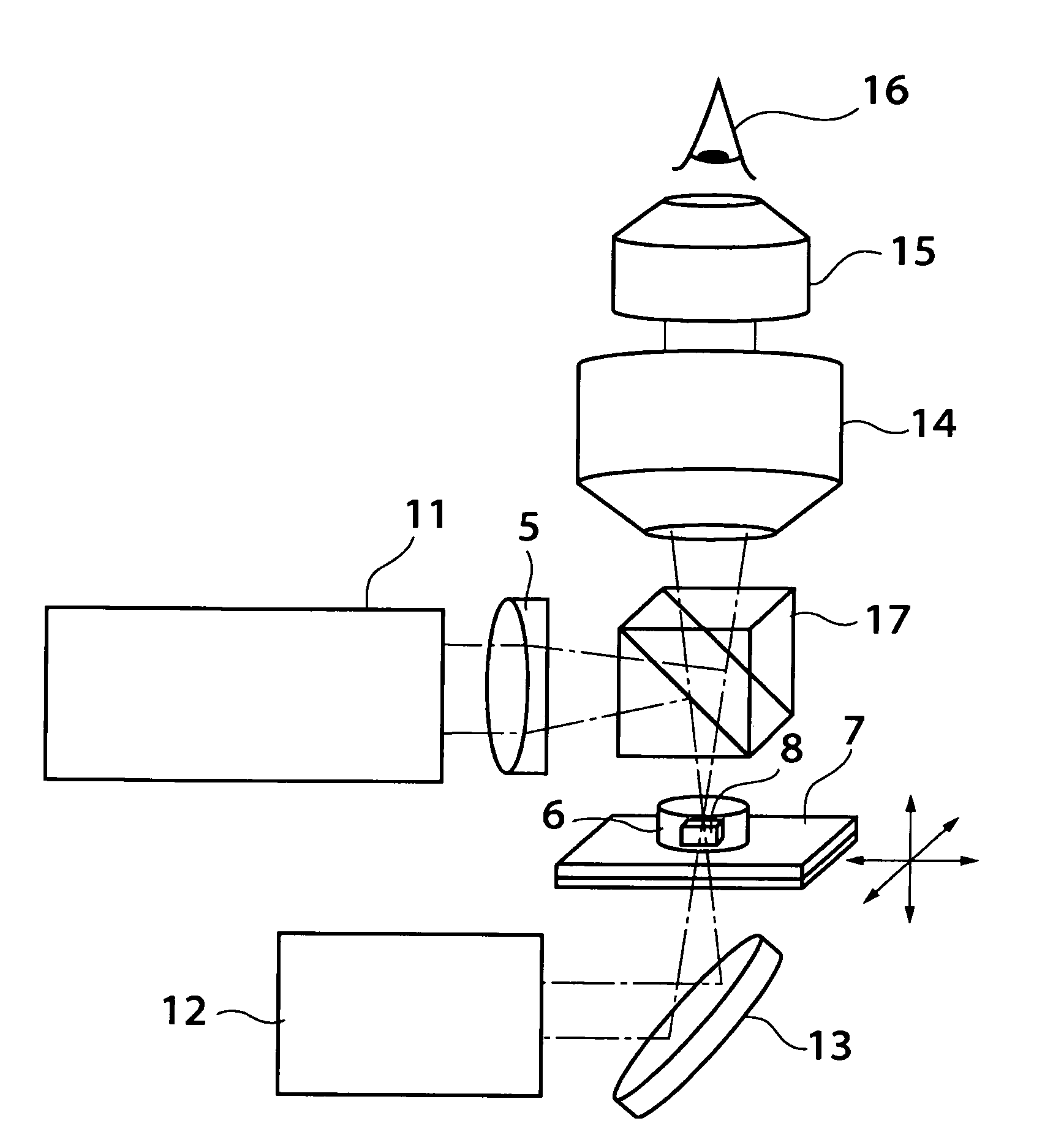
The ultraviolet short-pulse laser light emitted from the ultraviolet short-pulse laser light source 1 is focused on and caused to irradiate a macromolecular crystal 8 contained in a sample container 6 via a shutter 2, intensity adjusting element 3, irradiation position control mechanism 4, and focusing optical system 5. The sample container 6 is carried on a stage 7, and can be moved in three dimensions along the directions of the x, y and z axes in an x-y-z orthogonal coordinate system with the direction of the optical axis being taken as the z axis; furthermore, the sample container 6 can be rotated about the z axis. Working of the macromolecular crystal is performed by means of ultraviolet short-pulse laser light that is focused on and caused to irradiate the surface of the macromolecular crystal 8. In this way, various types of working can be securely performed on macromolecular crystals with little damage and by means of a simple operation.

Description

[0001]This is a continuation from PCT International Application No. PCT / JP2004 / 013577 filed on Sep. 10, 2004, which is hereby incorporated by reference.TECHNICAL FIELD[0002]The present invention relates to a macromolecular crystal working method, and more particularly relates to a method and apparatus for working a macromolecular crystal into a desired shape by irradiating the macromolecular crystal with focused ultraviolet short-pulse laser light, and also to a macromolecular crystal observation device that incorporates such a macromolecular crystal working apparatus.BACKGROUND ART[0003]In recent years, post-genome research known as proteome has been actively pursued. Something that has attracted particular attention in this research is research that attempts to elucidate the three-dimensional structure of proteins; such research is called “structural genome science.” Elucidation of the structures and functions of proteins is an important research field in the life sciences, and is...

Claims


Application Information

Patent Timeline
Patent Type & Authority Patents(United States)
IPC IPC(8): G02B6/00A61N5/00B23K26/00B23K26/02G02B6/26B23K26/04B23K26/08C08J3/28
CPCB23K26/0039B23K26/0066B23K26/0635B23K26/38B23K26/403B23K26/4065C08J3/28B23K26/0006B23K26/0624B23K26/352B23K2103/30B23K2103/42B23K2103/50
Inventor ADACHI, HIROAKIKITANO, HIROSHI
Owner NIKON CORP
Learn More