Silicon carbide Schottky diode and method of making the same

a silicon carbide and diode technology, applied in the field of silicon carbide schottky diode device forming method, can solve the problems of limiting the possible reverse breakdown voltage, poor structure, and inability to make p-type guard rings in a structure formed on a silicon carbide substra

Active Publication Date: 2008-05-06
CHIP INTEGRATION TECH
View PDF1 Cites 3 Cited by
  • Summary
  • Abstract
  • Description
  • Claims
  • Application Information

AI Technical Summary

Problems solved by technology

However, owing to the bipolar carriers characteristic of IGBT devices, the devices will suffer problems of the lifetime of the minority carriers while switching the device Consequently, if it is not possible to add lifetime killers in—during manufacturing, the system having IGBT devices would have to tolerate the power consumption and time waste while—switching IGBT devices.
Such a structure, however, has a very poor breakdown voltage.
As a result, the curved areas of the equipotential surfaces, have very strong field variations that limit the possible reverse breakdown voltage.
However, the p-type guard ring cannot be made in a structure formed on a silicon carbide substrate.
In fact, a diffusion annealing for a p-type dopant would require temperatures on the order of 1700° C., which raises acute technological problems.

Method used


Image

  • Silicon carbide Schottky diode and method of making the same
  • Silicon carbide Schottky diode and method of making the same
  • Silicon carbide Schottky diode and method of making the same

Examples


Embodiment Construction

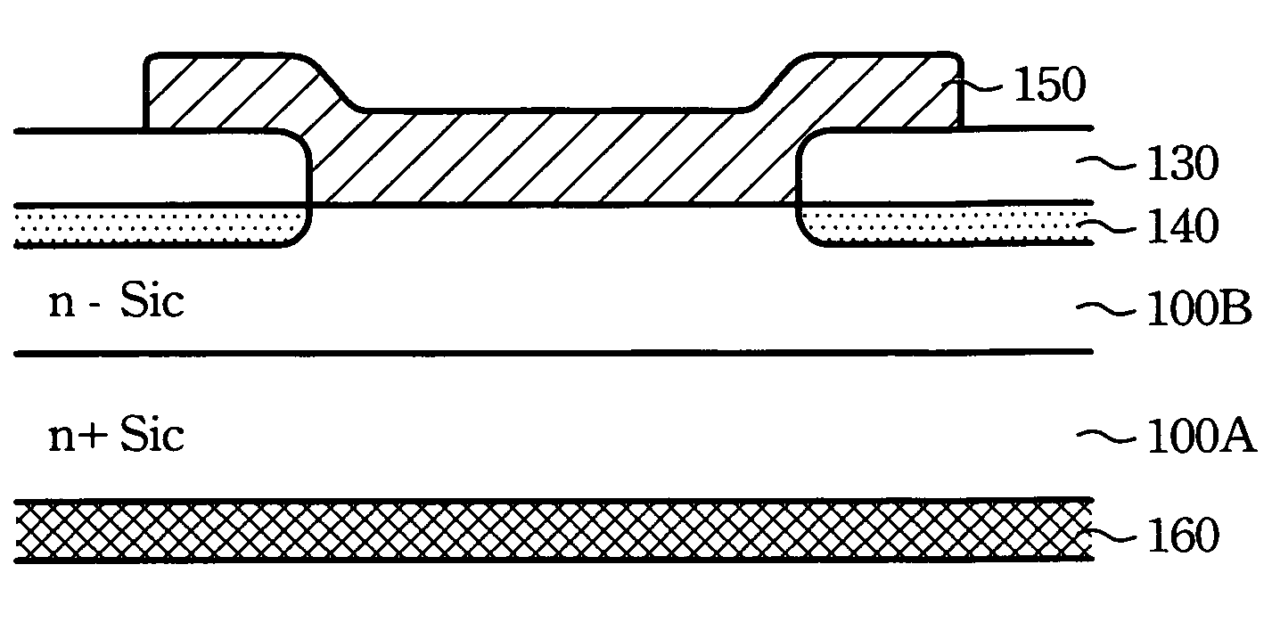
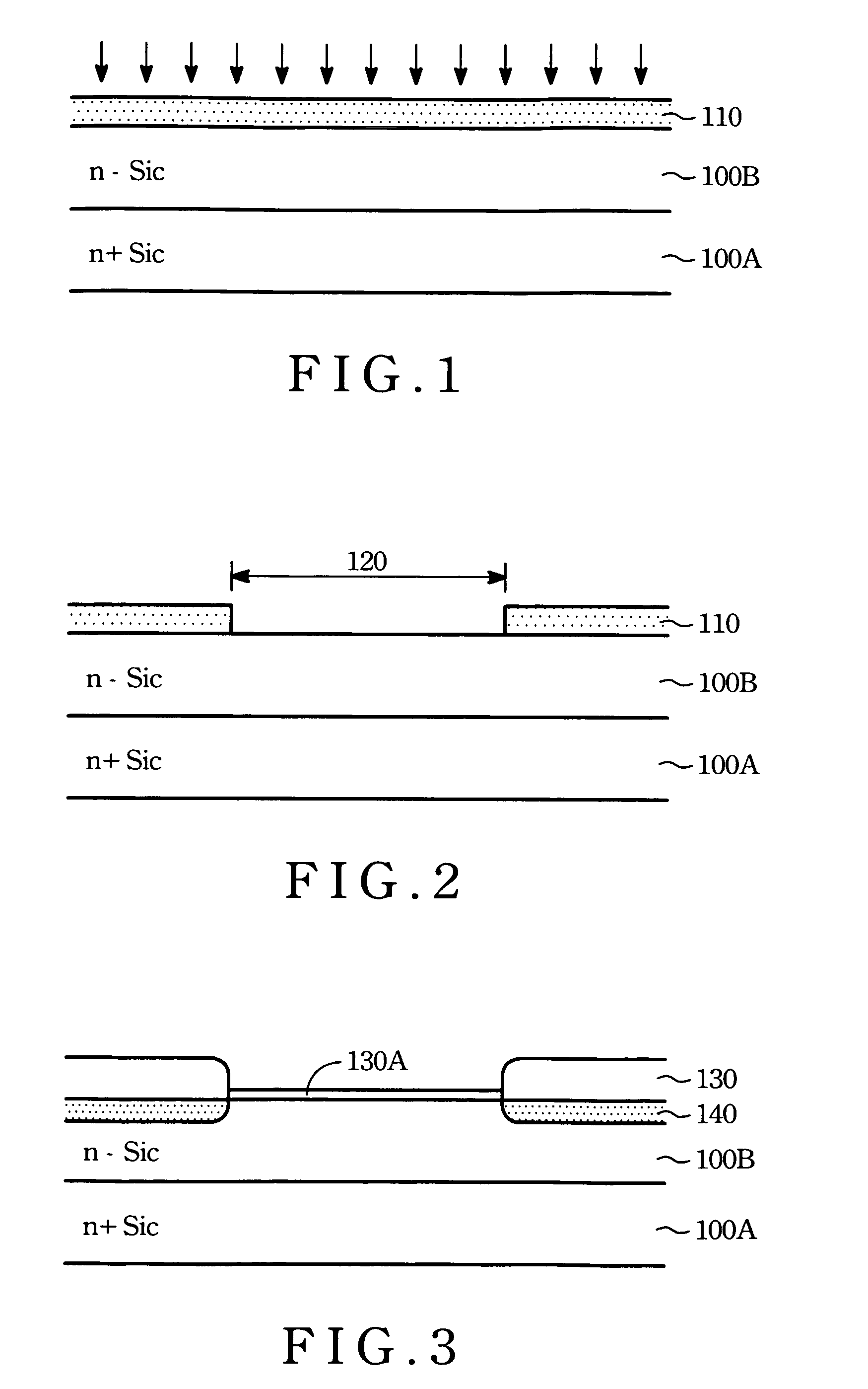
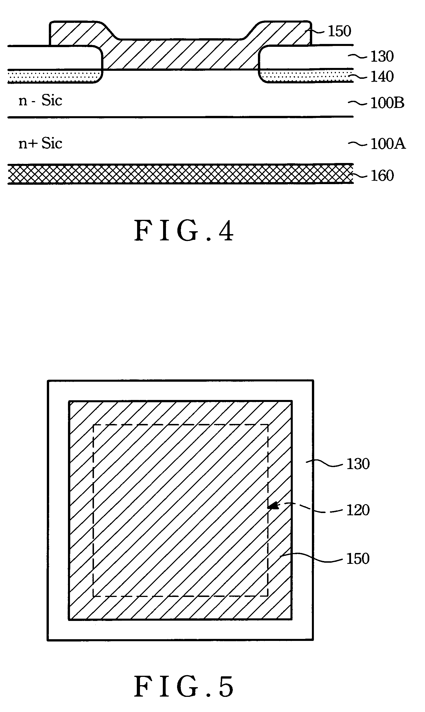
[0018]The method of forming Schottky diode according to the present invention is shown in cross-sectional views from FIG. 1 to FIG. 4.

[0019]Referring to FIG. 1, an n-type impurity heavily doped silicon carbide substrate 100A has an n-type impurity doped silicon carbide epi-layer 100B formed thereon is prepared. The epi-layer 100B functions as a drift layer 100B. An un-doped silicon layer 110 is then deposited on epi-layer 100B. The silicon layer can be selected from polycrystalline silicon or amorphous silicon.

[0020]Thereafter, an ion implantation is performed using p-type ion species to dope the silicon layer 110. The p-type ion species can be B+ or BF2+, aluminum ions, gallium ions, or indium ions.

[0021]Referring to FIG. 2, a patterning process to define an active region 120 is then followed by a lithographic and wet etching or dry etching of the silicon layer 110 until the drift layer 100B is exposed. Refering to FIG. 3, a thermal annealing process is conducted to form polyoxide ...


PUM

PropertyMeasurementUnit
temperatureaaaaaaaaaa
breakdown voltageaaaaaaaaaa
energy band gapaaaaaaaaaa

Abstract

A method of forming silicon carbide Schottky diode is disclosed. The processes required two photo-masks only. The processes are as follows: firstly, an n+-silicon carbide substrate having an n− silicon carbide drift layer is provided. Then a silicon layer is formed on the drift layer. An ion implant is carried out to dope the silicon layer. Afterward the doped silicon layer is patterned to define an active region. A thermal oxidation is then followed to form a thick oxide layer by oxidizing the silicon layer and form guard rings by using the doped silicon layer as a diffused source. The thin oxide layer on the drift layer is then removed by dilute HF dip or by BOE (buffer oxide etching) solution dip. Thereafter, a top metal layer is deposited and patterned to define as anode. After a backside layer removal, a metal layer served as cathode is formed.

Description

FIELD OF THE INVENTION[0001]The present invention relates to a semiconductor device, specifically, to a silicon carbide Schottky diode device forming method, whose formation processes require only two photo masks.BACKGROUND OF THE INVENTION[0002]Currently, in the power device market, power transistors with breakdown voltage over 100V are mostly occupied by silicon base insulated gate bipolar transistor (IGBT). However, owing to the bipolar carriers characteristic of IGBT devices, the devices will suffer problems of the lifetime of the minority carriers while switching the device Consequently, if it is not possible to add lifetime killers in—during manufacturing, the system having IGBT devices would have to tolerate the power consumption and time waste while—switching IGBT devices.[0003]By contrast, silicon base metal oxide semiconductor field transistors have a with mono-carrier species, and as a result, provide faster switch speed and less extra power consumption than those bipolar...

Claims


Application Information

Patent Timeline
Patent Type & Authority Patents(United States)
IPC IPC(8): H01L21/28H01L21/44
CPCH01L21/8213H01L29/6606H01L29/872H01L29/1608
Inventor WU, SHYE-LIN
Owner CHIP INTEGRATION TECH
Why Eureka
Try Eureka