Layer capacitor element and production process as well as electronic device
a production process and capacitor technology, applied in the field of capacitors, can solve the problems of reducing the performance of the capacitor, reducing the characteristics, and reducing the dielectric material, and achieve the effect of excellent high-frequency tracking performance and low characteristic deterioration
- Summary
- Abstract
- Description
- Claims
- Application Information
AI Technical Summary
Benefits of technology
Problems solved by technology
Method used
Image
Examples
first embodiment
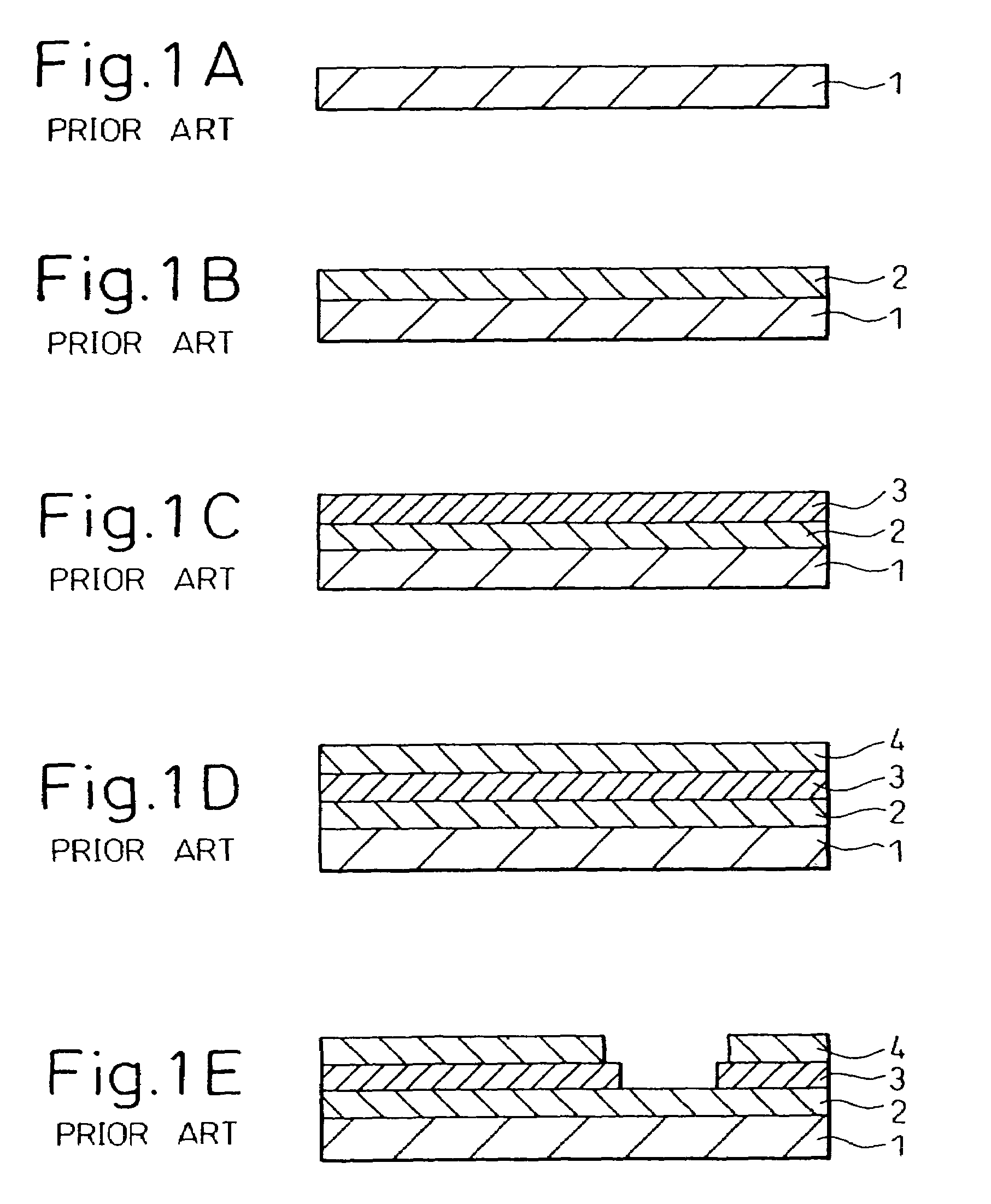
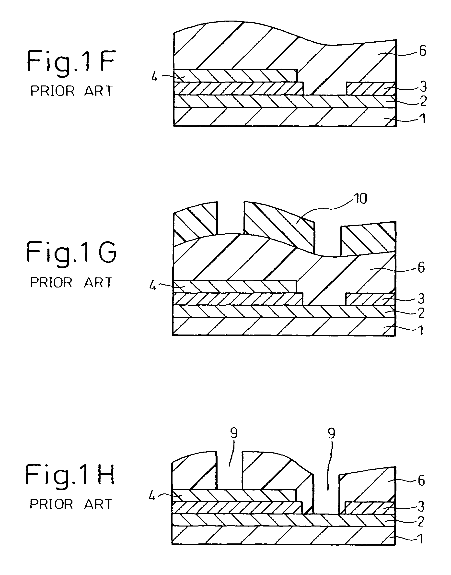
[0100]A thin layer capacitor element according to a first embodiment of the present invention will now be explained with reference to FIG. 5 and FIGS. 6A to 6J showing, in sequence the production process of the thin layer capacitor element.
[0101](1) Capacitor-Forming Step
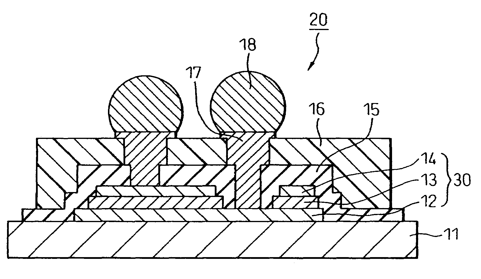
[0102]As shown in FIGS. 6A to 6D, a lower electrode layer 12 composed of platinum, a dielectric layer 13 composed of a composite oxide and an upper electrode layer 14 composed of platinum Pt are formed in that order on a silicon substrate 11 prepared as the supporting substrate, to form a capacitor 30 which is also referred herein to as a “capacitor structure”.
[0103]A metal oxide (such as BST) with a high dielectric constant is used herein as the material for the dielectric layer 13 to achieve downsizing and large capacitance.
[0104]Further, a precious metal such as platinum (Pt) or iridium (Ir), having excellent oxidation resistance in high temperature environments and allowing satisfactory crystal orientation contr...
second embodiment
[0154]A process for production of a thin layer capacitor element according to a second embodiment of the invention will now be explained.
[0155]The production process according to this embodiment can be carried out in accordance with the manner which is the same as that of the first embodiment described above with reference to FIGS. 6A to 6J. However, in this embodiment, formation of the dielectric layer 13 shown in FIG. 6C is carried out using a sputtering method in place of a sol-gel method, in contrast to the first embodiment. Also, a BST material in an amorphous state having the same composition as that of the dielectric layer 13 is used as the barrier layer 15 for the step of forming the barrier layer 15 shown in FIG. 6F.
[0156]First, a silicon wafer is used as the silicon substrate 11, and a sputtering method is used to form films of titanium oxide (TiO2; 20 nm) and platinum (Pt; 100 nm) in that order on the silicon wafer, as shown in FIGS. 6A to 6D, in the same manner as the fi...
third embodiment
[0165]A thin layer capacitor element according to a third embodiment of the invention will now be explained with reference to FIGS. 10 and 11, in which FIG. 10 is a perspective view of a thin layer capacitor element, and FIG. 11 is a cross-sectional view taken along line XI-XI of FIG. 10.
[0166]This embodiment is an application example of the thin layer capacitor element according to the first embodiment, and as shown in FIG. 10, a plurality of bumps are arrayed as terminals for the thin layer capacitor element 20 on one side of the thin layer capacitor element 20. The plurality of bumps 18 are arranged such that adjacent bumps are connected to different electrodes of the capacitor (capacitor structure) 30.
[0167]Specifically, each bump is electrically connected to every other electrode, and the connected capacitors 30 are internally connected together, as shown in FIG. 11.
[0168]For external connection of each bump, a bump 18a is connected to the power line of a circuit board (not sho...
PUM
| Property | Measurement | Unit |
|---|---|---|
| temperature | aaaaa | aaaaa |
| temperature | aaaaa | aaaaa |
| temperature | aaaaa | aaaaa |
Abstract
Description
Claims
Application Information
 - R&D
- Intellectual Property
- Life Sciences
- Materials
- Tech Scout
- Unparalleled Data Quality
- Higher Quality Content
- 60% Fewer Hallucinations
Browse by: Latest US Patents, China's latest patents, Technical Efficacy Thesaurus, Application Domain, Technology Topic, Popular Technical Reports.
© 2025 PatSnap. All rights reserved.Legal|Privacy policy|Modern Slavery Act Transparency Statement|Sitemap|About US| Contact US: help@patsnap.com


