
Integrated alkylation process using ionic liquid catalysts

a technology alkylation process, which is applied in the direction of organic chemistry, hydrocarbon oil treatment products, fuels, etc., can solve the problems of serious problems such as the inability to find uses for isopentane by-products, the significant amount of isopentane produced by refineries, and the inability to meet the requirements of ionic liquid catalyst requirements, etc., to achieve the effect of improving the operating efficiency of the refinery, reducing fuel gas production

Active Publication Date: 2008-10-07
CHEVROU USA INC
View PDF16 Cites 172 Cited by
  • Summary
  • Abstract
  • Description
  • Claims
  • Application Information

AI Technical Summary

Benefits of technology

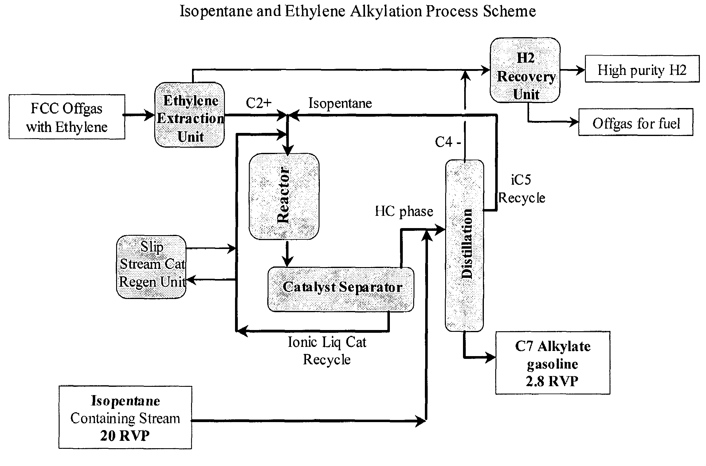
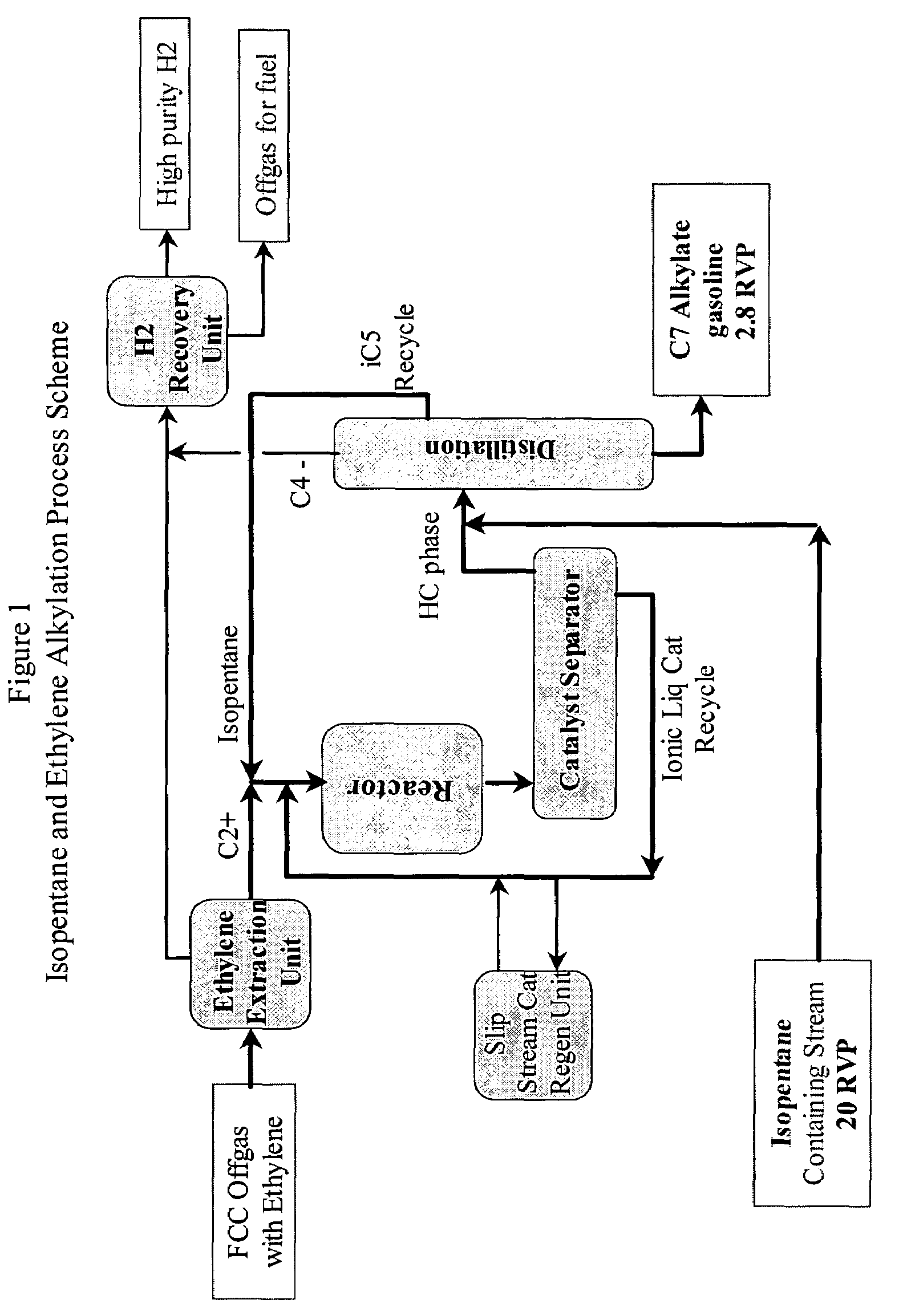
"The present invention is an integrated refinery process for producing high quality gasoline blending components with low volatility. The process involves separating a C2+ fraction from a first ethylene-containing refinery stream to produce a second refinery stream richer in ethylene than the first stream. An isopentane-containing refinery stream is then contacted with the second refinery stream in the presence of an ionic liquid catalyst in an alkylation zone under alkylation conditions. The resulting alkylation zone produces a high quality gasoline blending component of low volatility. This refinery process also reduces fuel gas production and produces high quality gasoline blending components with low volatility."

Problems solved by technology

As a result, these refineries produce a significant amount of isopentane.
As environmental laws began to place more stringent restrictions on gasoline volatility, the use of isopentane in gasoline was limited because of its high volatility.
As a consequence, the problem of finding uses for by-product isopentane became serious, especially during the hot summer season.
So, the gasoline volatility issue becomes even more serious, further limiting the usefulness of isopentane as a gasoline blending component.
Both of these processes require extremely large amounts of acid to fill the reactor initially.
The sulfuric acid plant also requires a huge amount of daily withdrawal of spent acid for off-site regeneration.
The necessity of having to handle a large volume of used acid is considered a disadvantage of the sulfuric acid based processes.
However, the aerosol formation tendency of HF presents a potentially significant environmental risk and makes the HF alkylation process less safe than the H2SO4 alkylation process.
Although these catalysts have been successfully used to economically produce the best quality alkylates, the need for safer and environmentally-more friendly catalyst systems has become an issue to the industries involved.

Method used


Image

  • Integrated alkylation process using ionic liquid catalysts
  • Integrated alkylation process using ionic liquid catalysts
  • Integrated alkylation process using ionic liquid catalysts

Examples


example 1

The Preparation of N-Butyl-Pyridinium Chloroaluminate Ionic Liquid

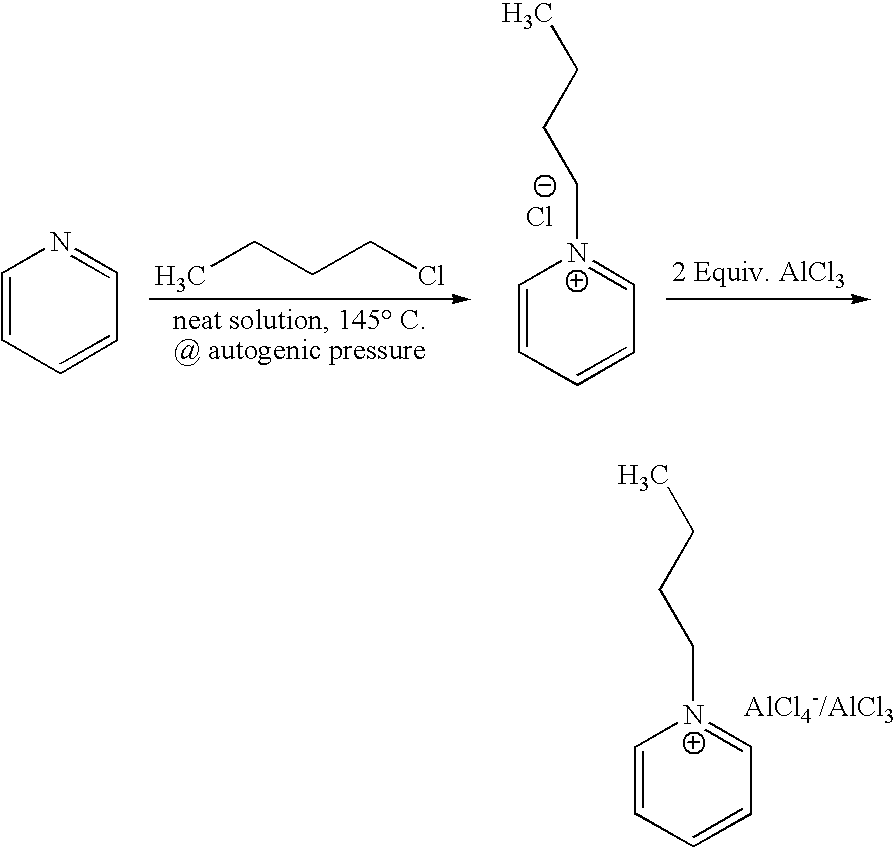
[0047]N-butyl-pyridinium chloroaluminate is a room temperature ionic liquid prepared by mixing neat N-butyl-pyridinium chloride (a solid) with neat solid aluminum trichloride in an inert atmosphere. The syntheses of butylpyridinium chloride and the corresponding N-butyl-pyridinium chloroaluminate are described below. In a 2-L Teflon-lined autoclave, 400 gm (5.05 mol.) anhydrous pyridine (99.9% pure purchased from Aldrich) were mixed with 650 gm (7 mol.) 1-chlorobutane (99.5% pure purchased from Aldrich). The neat mixture was sealed and let to stir at 145° C. under autogenic pressure over night. Then, the autoclave was cooled down to room temperature, vented and the resultant mixture was transferred to a three liter round bottom flask. Chloroform was used to rinse the liner and dissolve the stubborn crusty product that adhered to the sides of the liner. Once all transferred, the mixture was concentrated at reduced pres...

example 2

Batch Alkylation Run Procedure

[0049]Isopentane and ethylene batch alkylation was typically run at 50° C. with paraffin / olefin molar ratio of about 4. Under nitrogen atmosphere in a glove box, an autoclave vessel was charged with ionic liquid catalyst and anhydrous isopentane. The autoclave was then sealed and transferred to a hood and affixed to an overhead stirrer. Then, ethylene gas was introduced to the vessel. The autogenic pressure of the vessel usually rises to 2000 kPa to 24000 kPa depending on the amount of ethylene gas introduced into the autoclave. Once the reaction begins stirring (˜1200 rpm), the pressure quickly drops down to ˜900 kPa to 1100 kPa. The reaction is allowed to continue and stir until the pressure drops to 0 kPa to 70 kPa. Then, the stirring is stopped and the heating mantle is quickly removed. The autoclave is then cooled down to room temperature using a cooling coil. Then, a gas sample was drawn and the reactor is vented and weathered to relieve the syste...

example 3

Batch Alkylation of Isopentane in Butylpyridinium Chloroaluminate without Applying Any Additional Pressure (Only the Autogenic Pressure of the System)

[0050]Ethylene (9.5 gm) was alkylated with isopentane (103 gm) in 20 gm butylpyridinium chloroaluminate ionic at 50° C. and the autogenic pressure in a closed 300 cc autoclave fitted with an overhead stirrer and a cooling coil. The reaction was allowed to stir at ˜1200 rpm until no significant drop in pressure was noticeable. Table 1 below shows the reaction results.


PUM

PropertyMeasurementUnit
vol %aaaaaaaaaa
molar ratioaaaaaaaaaa
atmospheric pressureaaaaaaaaaa

Abstract

An integrated refining process for the production of high quality gasoline blending components from low value components is disclosed. In addition there is disclosed a method of improving the operating efficiency of a refinery by reducing fuel gas production and simultaneously producing high quality gasoline blending components of low volatility. The processes involve the alkylation of a refinery stream containing pentane with ethylene using an ionic liquid catalyst.

Description

FIELD OF THE INVENTION[0001]The present invention relates to an integrated refining process for the production of high quality gasoline blending components from low value components.BACKGROUND OF THE INVENTION[0002]Modern refineries employ many upgrading units such as fluidic catalytic cracking (FCC), hydrocracking (HCR), alkylation, and paraffin isomerization. As a result, these refineries produce a significant amount of isopentane. Historically, isopentane was a desirable blending component for gasoline having a high octane (92 RON), although it exhibited high volatility (20.4 Reid vapor pressure (RVP)). As environmental laws began to place more stringent restrictions on gasoline volatility, the use of isopentane in gasoline was limited because of its high volatility. As a consequence, the problem of finding uses for by-product isopentane became serious, especially during the hot summer season. Moreover, as more gasoline compositions contain ethanol instead of MTBE as their oxygen...

Claims


Application Information

Patent Timeline
Patent Type & Authority Patents(United States)
IPC IPC(8): C07C2/56C10L1/06
CPCC10G29/205C10G50/00C10L1/06C10G2400/02C10G2300/1081C10G2300/1088C10G29/12C07C2/56
Inventor TIMKEN, HYE KYUNG C.ELOMARI, SALEHTRUMBULL, STEVECLEVERDON, ROBERT
Owner CHEVROU USA INC
Learn More