
Electronic device, dielectric ceramic composition and the production method

a technology of dielectric ceramics and electronic devices, applied in the direction of fixed capacitors, natural mineral layered products, capacitor manufacture, etc., can solve the problems of short ir lifetime, reduced dielectric layers, and reduced specific resistance, and achieves ir temperature dependence, high specific permittivity, and improved tc bias characteristics

Active Publication Date: 2008-10-21
TDK CORPARATION
View PDF17 Cites 16 Cited by
  • Summary
  • Abstract
  • Description
  • Claims
  • Application Information

AI Technical Summary

Benefits of technology

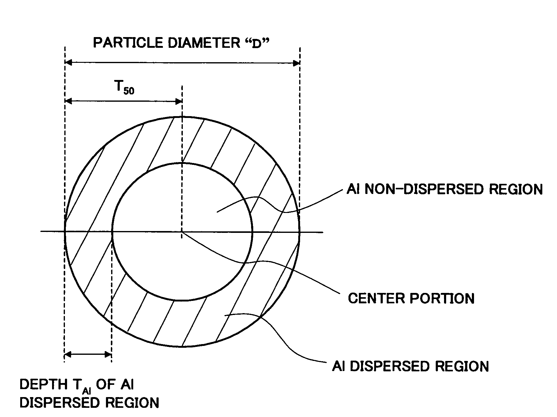
The present invention provides a dielectric ceramic composition with improved temperature characteristics and reduced bias characteristics. By configuring dielectric particles with a gradual decrease in Al concentration from the particle surface to inside, the TC bias characteristics can be reduced while maintaining a high specific permittivity. The composition also has a smaller size and can be used in electronic devices with a larger capacity. The invention also includes specific subcomponents that further improve the capacitor-temperature characteristics and the X7R standard. The dielectric ceramic composition can be used in multilayer ceramic capacitors and has a compact body with a thinner layer.

Problems solved by technology

However, when fired in a reducing atmosphere, the dielectric layers are reduced and the specific resistance declines.
However, a multilayer ceramic capacitor using a reduction-resistant dielectric material has disadvantages that a decline of IR (insulation resistance) is remarkable when an electric field is applied, the IR lifetime is short and the reliability is low.
Recently, there is a tendency of reducing a wire harness for connecting the electronic apparatus and an apparatus to be controlled thereby and the electronic apparatus may be provided outside of a vehicle, therefore, environments for the electronic apparatuses have been getting more severe.
However, the dielectric ceramic compositions in The Japanese Patent Publication No. 3348081 and The Japanese Patent Publication No. 3341003 had disadvantages that the TC bias characteristics (capacity-temperature characteristics when applied with a direct-current voltage) were poor and the IR temperature dependency from the room temperature to a high temperature part was poor, so that the practical use as a product sometimes became difficult.

Method used


Image

  • Electronic device, dielectric ceramic composition and the production method
  • Electronic device, dielectric ceramic composition and the production method
  • Electronic device, dielectric ceramic composition and the production method

Examples


first embodiment

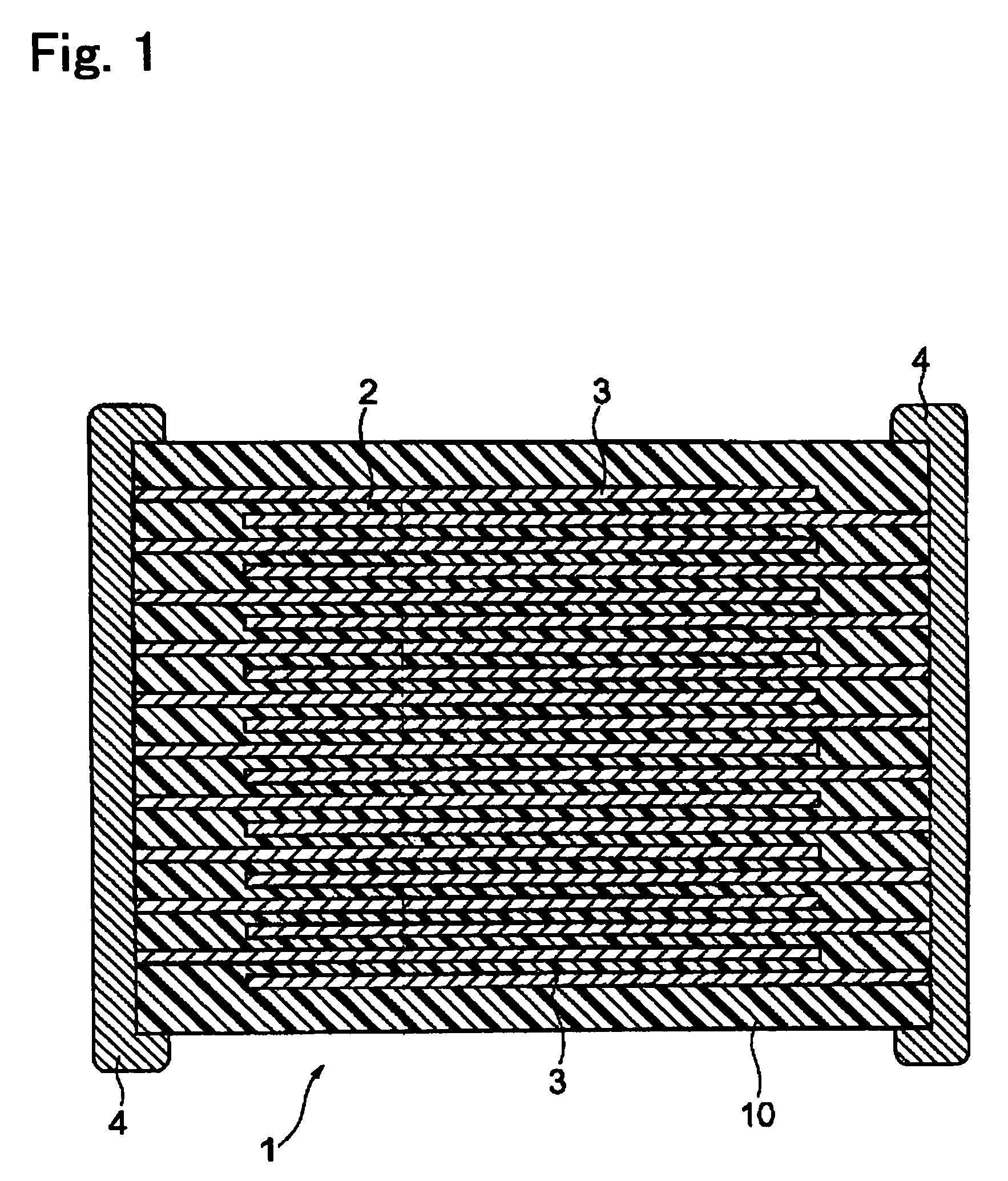
[0058]As shown in FIG. 1, a multilayer ceramic capacitor 1 as an electronic device according to an embodiment of the present invention has a capacitor element body 10, wherein dielectric layers 2 and internal electrode layers 3 are alternately stacked. Both end portions of the capacitor element body 10 are formed with a pair of external electrodes 4 respectively conducting to the internal electrode layers 3 arranged alternately in the element body 10. The internal electrode layers 3 are stacked, so that the respective end surfaces are exposed alternately to surfaces of two facing end portions of the capacitor element body 10. The pair of external electrodes 4 are formed on both end portions of the capacitor element body 10 and connected to the exposed end surfaces of the alternately arranged internal electrode layers 3, so that a capacitor circuit is configured.

[0059]A shape and size of the capacitor element body 10 are not particularly limited and may be suitably set in accordance ...

second embodiment

[0147]Comparing with the first embodiment, in the second embodiment, a composition of a dielectric ceramic composition composing the dielectric layers 2 is different in points explained below. Other than that, the second embodiment has the same configuration and effects as those in the first embodiment and the duplicate explanation will be omitted.

[0148]Namely, in the second embodiment, in addition to the main component, an Al oxide, the first to third and fifth to seventh subcomponent explained in the first embodiment, a fourth subcomponent including an oxide of R1 (note that R1 is at least one kind selected from Sc, Er, Tm, Yb and Lu) is included.

[0149]The fourth subcomponent (an oxide of R1) exhibits an effect of shifting the Curie's temperature to the high temperature side and an effect of flattening the capacitor-temperature characteristics. A content of the fourth subcomponent is preferably 0.5 to 7 moles, and more preferably 0.5 to 5.0 moles in terms of an R1 element with res...

example 1

[0155]In the example 1, multilayer ceramic capacitor samples corresponding to the first embodiment (the X7R characteristics) were produced and evaluated.

[0156]First, 100 moles of BaTiO3 as a main component material and 2.0 moles of Al2O3 were prepared. Next, these materials were mixed to obtain powder before calcining, and calcining is performed thereon under the condition below, so as to obtain five different kinds of powders calcined at different temperatures (corresponding to samples 1 to 5 in Table 1).

[0157]Calcining temperature: temperatures between 700 and 1000° C.

[0158]Calcining time: two hours

[0159]Note that the calcining temperatures of the respective samples were 700° C. in a sample 1, 750° C. in a sample 2, 800° C. in a sample 3, 850° C. in a sample 4 and 1000° C. in a sample 5.

[0160]Next, the obtained preliminarily fired powders were pulverized, added with subcomponents below, wet mixed by a ball mill for 16 hours and dried to obtain dielectric materials (dielectric cera...


PUM

PropertyMeasurementUnit
capacity-temperatureaaaaaaaaaa
capacitor-temperatureaaaaaaaaaa
capacitor-temperature characteristicsaaaaaaaaaa

Abstract

A dielectric ceramic composition comprising a main component including barium titanate and an oxide of Al, wherein the dielectric ceramic composition includes a plurality of dielectric particles, concentration of Al in each of the dielectric particles becomes lower from a particle surface to inside thereof, and each of the dielectric particles has an Al non-dispersed region substantially not including Al at least at a center portion of the particle.

Description

BACKGROUND OF THE INVENTION[0001]1. Field of the Invention[0002]The present invention relates to a dielectric ceramic composition having reduction resistance and an electronic device, such as a multilayer ceramic capacitor, using the dielectric ceramic composition.[0003]2. Description of the Related Art[0004]A multilayer ceramic capacitor as an electronic device is widely used as a highly reliable compact electronic device having a large capacity and by a large number in one electronic apparatus. In recent years, as the apparatuses become more compact and higher in performance, demands for a multilayer ceramic capacitor to be more compact with a larger capacity, low at cost and higher in reliability have become still stronger.[0005]A multilayer ceramic capacitor is normally produced by using internal electrode layer paste and dielectric layer paste, stacking them by using a sheet method or a printing method, etc. and co-firing internal electrode layers and dielectric layers in an ob...

Claims


Application Information

Patent Timeline
Patent Type & Authority Patents(United States)
IPC IPC(8): C04B35/468H01G4/06H01B3/12H01G4/12H01G4/30H01G13/00
CPCC04B35/62685C04B35/628C04B35/62813C04B35/6303C04B35/64H01G4/1227H01G4/30C04B35/4682B32B2311/22Y10T428/2993C04B2235/3203C04B2235/3205C04B2235/3206C04B2235/3208C04B2235/3213C04B2235/3215C04B2235/3217C04B2235/3224C04B2235/3225C04B2235/3239C04B2235/3241C04B2235/3244C04B2235/3249C04B2235/3256C04B2235/3258C04B2235/3262C04B2235/3409C04B2235/3418C04B2235/3436C04B2235/3454C04B2235/6582C04B2235/6584C04B2235/6588C04B2235/663C04B2237/346C04B2237/405H01G4/018H01G4/10
Inventor ITO, KAZUSHIGESATO, AKIRA
Owner TDK CORPARATION
Learn More