

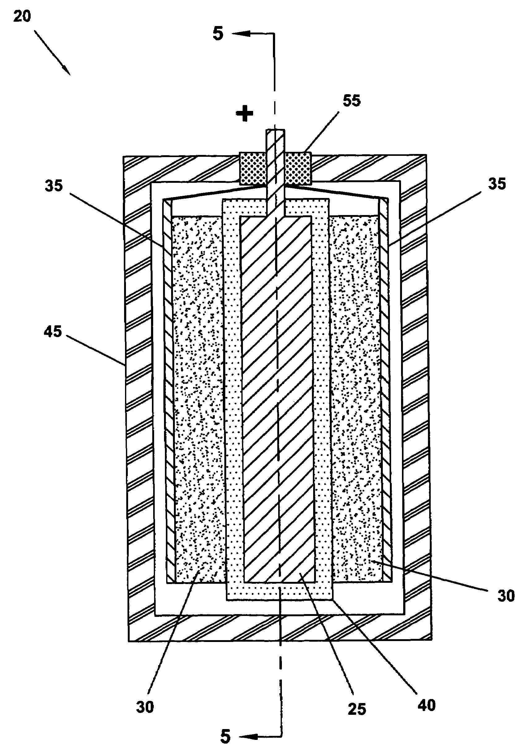
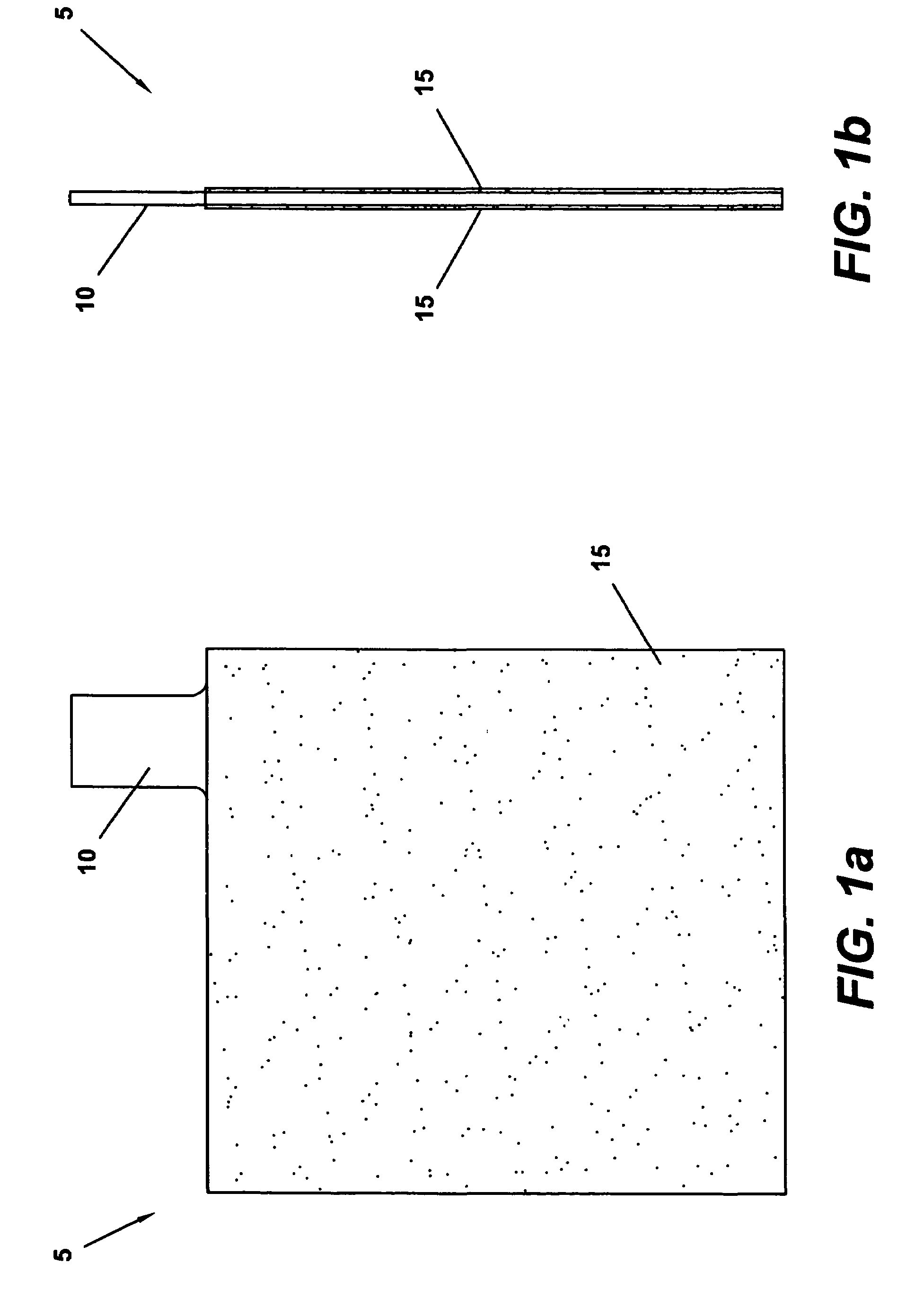
Current collector for a double electric layer capacitor
a current collector and capacitor technology, applied in the field of electrochemical capacitors, can solve the problems of low stability, low specific resistance of thin oxidation layer, low operating stability, and reliability, and achieve high over-voltage of hydrogen and oxygen gassing, low cost, and convenient use.
- Summary
- Abstract
- Description
- Claims
- Application Information
AI Technical Summary
Benefits of technology
Problems solved by technology
Method used
Image

Examples
example 1
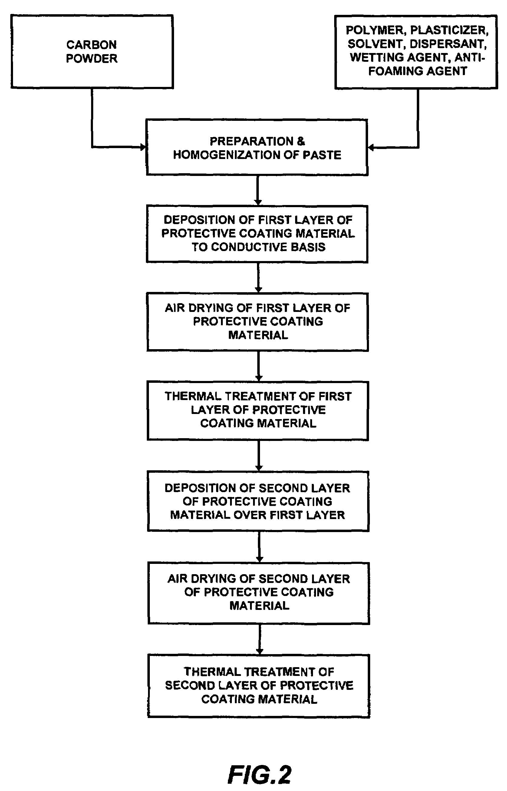
[0048]An exemplary current collector was manufactured according to the technique described above. The current collector had conductive basis dimensions of approximately 135×72×0.2 (mm). A protective coating material was deposited to the conductive basis in two separate layers, such that the final protective layer thickness was approximately 50 μm. The conductive basis was manufactured from a lead alloy, namely an alloy comprised of approximately 97% lead and approximately 3% tin. The composition of the current collector protective coating paste was approximately 6.0 weight % carbon powder; 5.2 weight % perchlorovinyl polymer; 8.2 weight % plasticizer; 80 weight % solvent (acetone, n-butyl acetate, toluol); 0.3 weight % dispersant; 0.15 weight % wetting agent (surfactant); and 0.15 weight % antifoaming agent. After thermal treatment of the second of the two protective coating material layers, the composition of the protective layer was 30 weight % carbon powder; 45 weight % perchloro...
example 2
[0069]Another exemplary current collector was manufactured in a manner similar to that described above. The current collector again had conductive basis dimensions of approximately 135×72×0.2(mm). A protective coating material was deposited to the conductive basis in two separate layers, such that the final protective layer thickness was approximately 50 μm. The conductive basis was manufactured from a lead alloy, namely an alloy comprised of approximately 99% lead and approximately 1% tin. The composition of the current collector protective coating paste was approximately 4.0 weight % carbon powder; 9.7 weight % perchlorovinyl polymer; 6.0 weight % plasticizer; 80 weight % solvent (acetone, n-butyl acetate, toluol); 0.1 weight % dispersant; 0.1 weight % wetting agent (surfactant); and 0.1 weight % antifoaming agent. After thermal treatment of the second of the two protective coating material layers, the composition of the protective layer was 20 weight % carbon powder; 52 weight % ...
PUM
| Property | Measurement | Unit |
|---|---|---|
| pore diameter | aaaaa | aaaaa |
| temperature | aaaaa | aaaaa |
| temperature | aaaaa | aaaaa |
Abstract
Description
Claims
Application Information