
Method of making a sliding bearing

a technology of sliding bearing and bearing surface, which is applied in the direction of sliding contact bearings, manufacturing tools, machines/engines, etc., can solve the problems of surface stiction, high cost, and high cost of bearing substrate, and achieves sufficient structural strength, resists wear, and improves performance and cost. the effect of the bearing substra

Inactive Publication Date: 2008-12-02
FEDERAL MOGUL WORLD WIDE LLC
View PDF13 Cites 34 Cited by
  • Summary
  • Abstract
  • Description
  • Claims
  • Application Information

AI Technical Summary

Benefits of technology

[0018]The proposed surface structures will settle the dilemma imposed by the convention of continuous uniform surface. Separate surface elements with different materials are so designed as to satisfy conflicting surface requirements. The proposed surface structure with relative thin / pattered layers and different materials from the substrate materials will settle the dilemma; thus, the engineered surfaces can give better performance to retain lubricants, pumping lubricant, and resist wear without compromising the performance and cost of the bearing substrate. Unlike the surface, the bearing substrate needs to have sufficient structural strength instead of wear resistance and lubricant enhancement. The materials conflict can be satisfied by the composite surface.
[0019]Advanced materials processing technologies are necessary to realize these surfaces. These processes include electrochemical, electro-plasma, and photo-dielectric lithography, etc. Optimal combination of several processes is organized to achieve the best production efficiency and lowest cost. Advanced materials processing technologies are necessary to realize these surfaces. These processes include electrochemical, electrophoretic, electro-plasma, electrostatic, and photo-dielectric lithography, etc. The combination of several processes is optimized to achieve the best production efficiency and lowest cost.

Problems solved by technology

Other bearings move slowly enough, or intermittently, or under sufficiently light loads so that separation by a film of lubricant is not necessary for satisfactory performance and life.
As to cost, sliding bearings can frequently be produced at very small cost in mass-production quantities, but their cost can be very large, when they have to be produced in small quantities for special designs.
For all applications of these sliding bearing types, friction loss and wear are two major challenges for the bearings and bearing surfaces.
This is particularly the case in harsh application environments, such as is the case with the many types of sliding bearings used in automotive vehicle applications, such as those that are subjected to reciprocal or sliding motion in engines, as well as other friction / wear systems and other motion systems.
However, a phenomenon frequently described as surface stiction can occur if the contacting surfaces are too smooth and the bearing surface contact area is too large.
Furthermore, hard materials are frequently not suitable for use as bearing materials because they generally have low fracture toughness.
The use of various hard coatings for bearing surfaces have been proposed, but they are also known to be prone to failure under high surface stress conditions due to low fracture toughness or problems associated with the adhesion of the bearing surface coating to the underlying bearing material.
Further, they frequently have required extensive preparation of the bearing surface, as by drilling, forming or otherwise preparing the bearing surface to receive the raised projection, or manual or other restrictive methods of applying the raised projections to the bearing surface.
The conventional processes can only fabricate macro features on the bearing parts.
The process is not sufficiently flexible and efficient for many surface designs, which require thin layers and complex surface patterns.
The conventional method also put too much surface materials on the part and reduces the performance of substrate because the surface materials does not perform as good as the substrate materials.

Method used


Image

  • Method of making a sliding bearing
  • Method of making a sliding bearing
  • Method of making a sliding bearing

Examples


Embodiment Construction

[0033]The present invention is a method of making a sliding bearing having a bearing surface which includes at least one of bearing surface feature which is located in and extends upwardly from a corresponding plurality of cavities formed in the bearing surface. The at least one bearing surface feature is preferably made from a bearing surface material and formed in a predetermined pattern so as to improve at least one of the friction and wear characteristics of the bearing surface, and consequently of the bearing also.

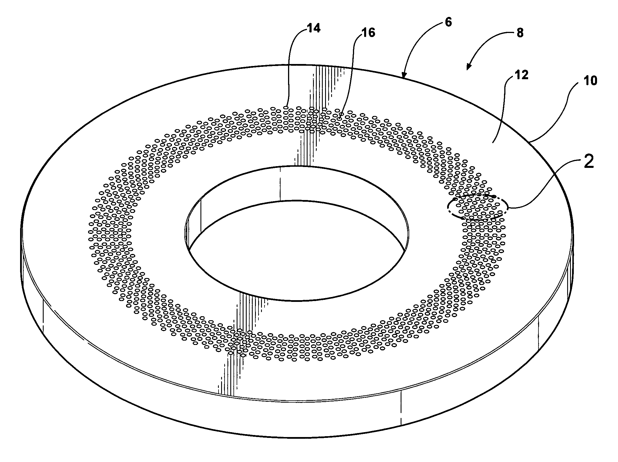
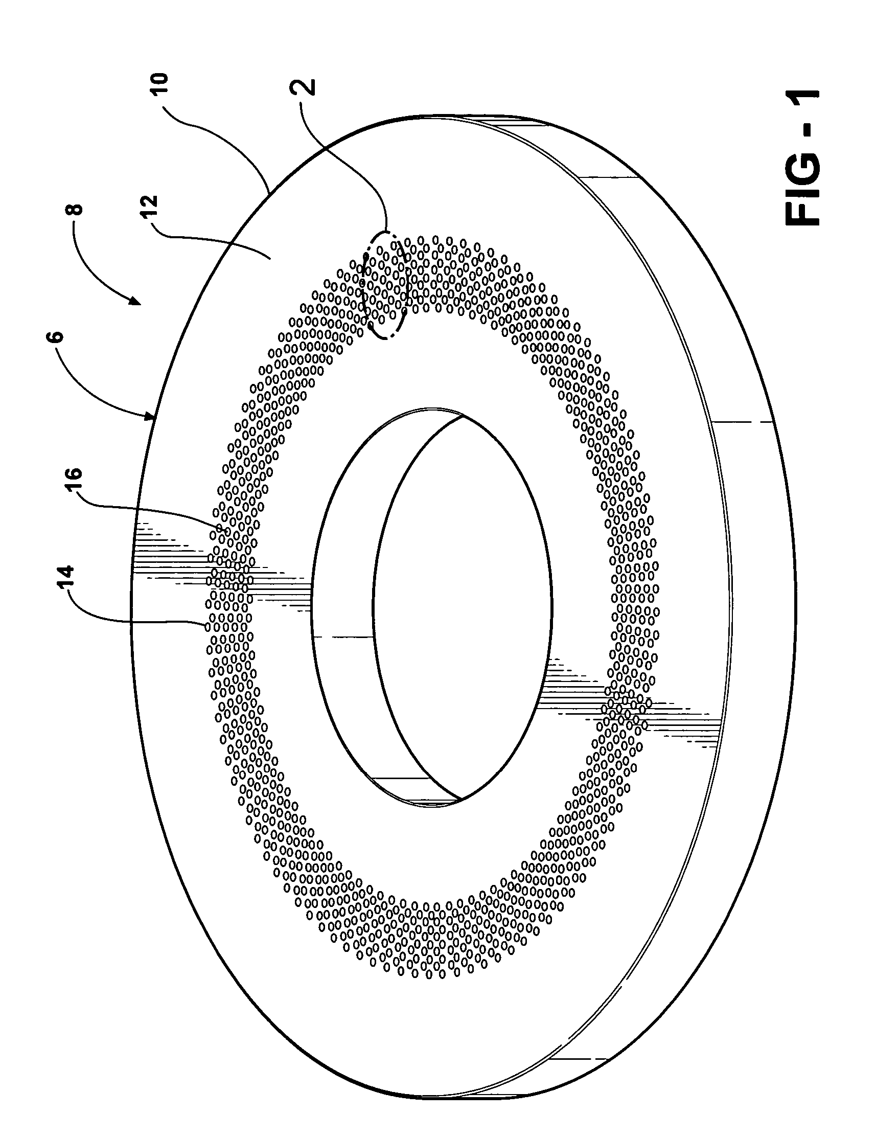
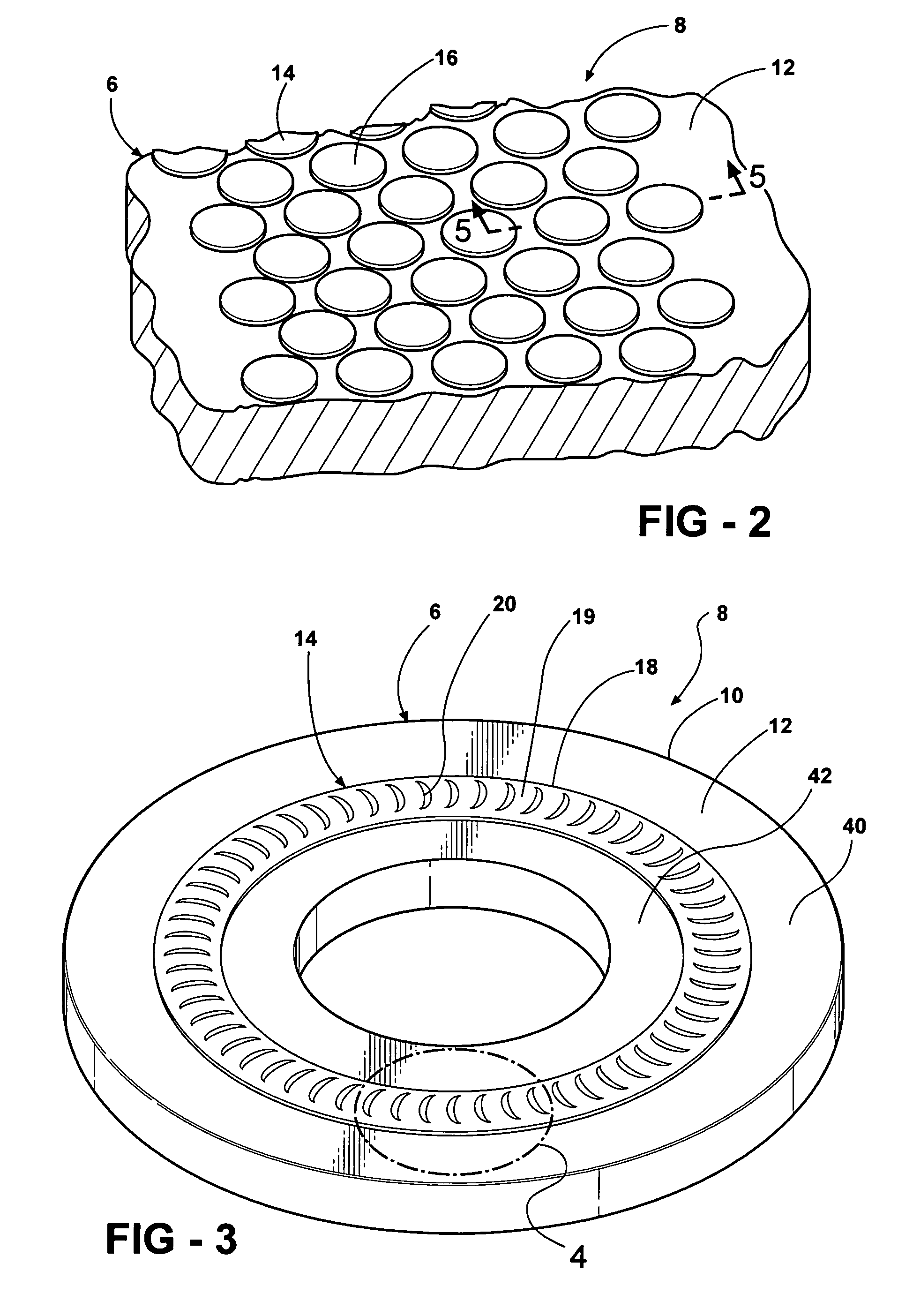
[0034]FIGS. 1-2 and FIGS. 3-4 illustrate two examples, respectively, of a bearing having at least one bearing surface feature which may be made by the method of the present invention. FIGS. 1-2 illustrate one example of bearing element 6 of a sliding bearing 8 in the form of a thrust washer 10 having a bearing surface 12 which includes a plurality of bearing surface features 14 in the form of cylindrical pads 16. These features 14 are located within a plurality of cor...


PUM

PropertyMeasurementUnit
adhesionaaaaaaaaaa
electrically conductiveaaaaaaaaaa
photosensitiveaaaaaaaaaa

Abstract

This invention introduces a new category of engineered surfaces and corresponding production processes for better wear resistance and lower friction loss. The structured surfaces can be applied on many automobile components with frictional surfaces. The composite structure settles the usual conflicts between surface functions and stresses. Two sets of multiple-step processes are introduced to achieve high production efficiency and low cost. Unlike traditional surface technologies that generate single and uniform layers on the whole part surface, the new technology processes the part surface selectively for more effective surfaces with versatile functions.

Description

BACKGROUND OF THE INVENTION[0001]1. Technical Field[0002]This invention relates generally to a method modifying a bearing surface of a sliding bearing member. More particularly, it relates to a method of adding at least one surface feature as a coating to a wear surface by selective deposition of the coating in the shape of the feature on the bearing surface.[0003]2. Related Art[0004]A bearing is defined in a general sense as a means of positioning one member with respect to another member in such a way that relative motion of the members is possible. The members have respective bearing surfaces which are in bearing contact with one another, typically through a lubricant which is used to promote the relative movement of the members, reduce wear of the bearing surfaces, reducing corrosion and for other purposes. The relative motion of the bearing surfaces and the bearing type are dictated by the requirements of the application of which the bearing surfaces will be a part. Bearings an...

Claims


Application Information

Patent Timeline
Patent Type & Authority Patents(United States)
IPC IPC(8): B21D53/10B21B1/46F16C1/24F16C32/06F16C33/00F16C33/02F16C33/10
CPCB21D53/10F16C17/02F16C17/035F16C17/04F16C17/065F16C33/103F16C33/1075F16C33/24F16C41/008B23P15/003Y10T29/49636F02F1/20F02F3/10Y10T29/49709Y10T29/49705Y10T29/4998F16C33/26F16C33/02F16C17/00F16C33/62F16C33/00
Inventor LUO, YUEFENGFREEMANTLE, PAULZDEBLICK, WILLIAM
Owner FEDERAL MOGUL WORLD WIDE LLC
Learn More