
Active radical initiator for internal combustion engines

a technology of active radicals and internal combustion engines, which is applied in the direction of machines/engines, mechanical equipment, electric control, etc., can solve the problems of increased nitric oxide and particulate matter emissions, start-ability, specific power output, poor fuel economy and drive-ability,

Inactive Publication Date: 2008-12-16
YU ROBERT C +2
View PDF13 Cites 24 Cited by
  • Summary
  • Abstract
  • Description
  • Claims
  • Application Information

AI Technical Summary

Benefits of technology

"The present invention provides a device that separates the high temperature combustion chemical reaction of the main fuel charge from the low temperature pre-ignition chemical reaction process and controls the ignition timing of the main fuel charge with minimum or no ignition delay. The device allows the pre-ignition chemical reaction to proceed efficiently inside the device without any auxiliary compressed air supply or electrical heating element. The device produces multiple active radical plumes at a desired moment to attack the main fuel charge in a lean fuel air mixture and / or cold environments to achieve a fast energy release in the main fuel charge for high cycle efficiency and a low peak combustion temperature, resulting in very low NOx emissions. The device can control the start of ignition of the main fuel charge independent of the conditions of the main fuel charge mixture inside the combustion chamber in order to avoid engine knocking and excessive mechanical loading on the engine structure. The device can allow gasoline engines to significantly improve fuel economy, exhaust emissions, and achieve diesel-like lean operation, substantially no throttling loss, and no need for a spark plug. The device can be used as a cold starting aid or a cold start white smoke control device by an instant ignition of the main fuel charge mixture at relatively low compression temperatures caused by a low ambient temperature condition while avoiding the need for using a glow plug, an intake air heater, or an increased engine compression ratio. The device can be applied independently in all petroleum or non-petroleum based fuel engines including gasoline, diesel, propane, kerosene, natural gas, hydrogen, methanol, ethanol, and others."

Problems solved by technology

The compression ignition direct injection (CIDI) diesel engine burns 30% to 50% less fuel as compared to a similar size homogeneous charge spark ignition (HCSI) gasoline engine, but with the disadvantages of increased nitric oxide and particulate matter emissions, start-ability, and specific power output.
On the other hand HCSI gasoline engines offer the advantages of lower nitric oxide and particulate matter emissions, improved start-ability, and specific power output, but with poor fuel economy and drive-ability.
Significant challenges include controlling ignition timing and burn rate over all engine operating conditions, poor cold starts and transient response, and high hydrocarbons and carbon mono-oxide emissions.
However, due to the transient nature of the IC engines with continuous changing of engine operating and boundary conditions, experts in the field have been unable to control compression ignition timing by directly managing the conditions and composition of the main fuel charge through the whole cycle of intake and compression strokes.
Unless the ignition delay can be fixed or made to be near zero, the start of ignition cannot be controlled completely by the injection timing of the main fuel charge.
Uncontrolled ignition timing leads to an uncontrolled combustion and excessive engine knocking.
Many attempts to control the compression ignition timing of a conventional direct injection diesel engine by managing directly the conditions and composition of the main charge have been unsuccessful.
Others were to heat up the fuel spray to improve the pre-ignition process through the use of electrical heating elements but at the expense of operational safety, very high unburned hydrocarbon emissions, and compromising the main fuel charge injection characteristics (see U.S. Pat. Nos. 4,603,667; 4,787,349; 4,926,819; 6,722,339; 6,289,869, and 6,378,485).
All such systems are simply not rapid and flexible enough to achieve the right conditions of temperature, pressure and mixture composition histories for a controlled ignition process.
In addition, a compromise on the main injection characteristics can lead to a poor main combustion process and to very high smoke.

Method used


Image

  • Active radical initiator for internal combustion engines
  • Active radical initiator for internal combustion engines
  • Active radical initiator for internal combustion engines

Examples


Embodiment Construction

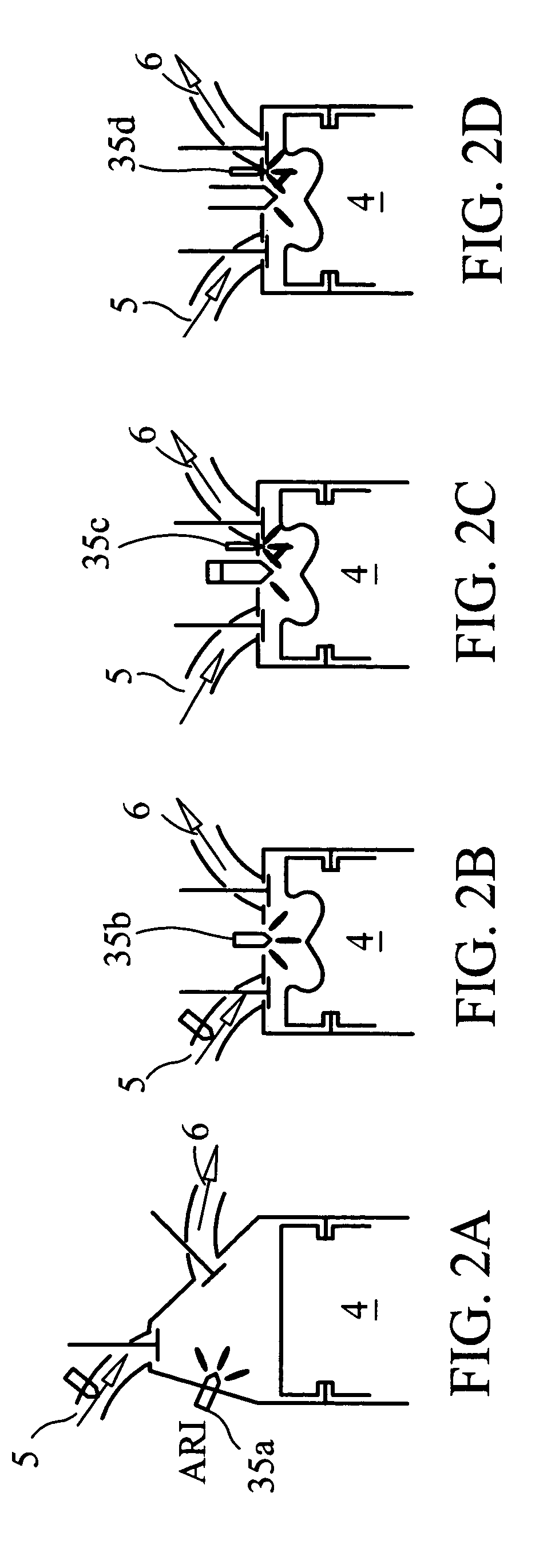
[0025]In one embodiment, the invention separates the high temperature combustion chemical reaction of the main fuel charge from the low temperature pre-ignition chemical reaction process. This is done by the use of an active radical initiator (ARI), in conjunction with a relatively low compression temperature and / or very lean fuel air mixture inside the main combustion chamber.

[0026]The pre-ignition chemical reaction process of the main charge is made irrelevant by operating the main fuel charge at conditions too lean and / or too cold to ignite, such that without the onset of initiator's multiple active radical plumes of the present invention, the ignition of main charge will not generally occur. A lean fuel air mixture is generally required for a high cycle efficiency and very low emissions engine.

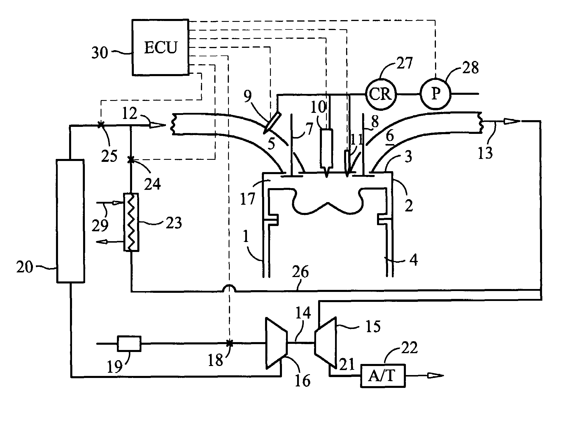
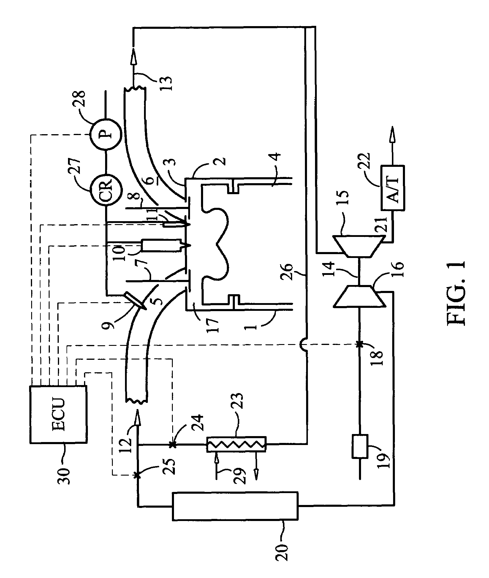
[0027]FIG. 1 depicts schematically and in cross section a portion of an internal combustion engine pertaining to one embodiment of the present invention. The internal combustion engine is ...


PUM


Abstract

In an internal combustion engine a fuel-air mixture having compression temperatures and pressures sufficiently low as not to support auto ignition, ignition is achieved by injecting igniting active radicals into the air-fuel mixture. In one embodiment the active radicals are provided by withdrawing a portion of the mixture, treating it to produce active radicals in the portion and returning the portion to the mixture. Treatment of the portion typically includes simultaneously injecting, mixing, and compression of a predetermined amount of pilot fuel within the portion.

Description

CROSS-REFERENCE TO RELATED APPLICATIONS[0001]The present application claims the benefit of U.S. Provisional Patent Application No. ED 500647120US filed 10 Jan. 2005, which is hereby incorporated by reference.TECHNICAL FIELD[0002]The present invention relates to combustion systems in internal combustion engines.BACKGROUND OF THE INVENTION[0003]Internal combustion (IC) engines have been the prime mover for more than a century. Nevertheless there remain opportunities for continuous improvement in key engine attributes such as specific power output, fuel economy, and exhaust emissions. The present invention represents an important discovery in the IC engine technologies to improve the above-mentioned attributes. The compression ignition direct injection (CIDI) diesel engine burns 30% to 50% less fuel as compared to a similar size homogeneous charge spark ignition (HCSI) gasoline engine, but with the disadvantages of increased nitric oxide and particulate matter emissions, start-ability,...

Claims


Application Information

Patent Timeline
Patent Type & Authority Patents(United States)
IPC IPC(8): F02M43/00F02B13/00
CPCF02D41/3047F02M43/04F02B1/12F02B29/0406F02B2275/14F02M25/0707F02M25/0727F02M47/027F02M51/061F02M61/042F02M63/001F02M69/046Y02T10/128Y02T10/123F02M26/05F02M26/23Y02T10/12
Inventor YU, ROBERT C.YU, MING-LI HSUYU, JR., ROBERT C.
Owner YU ROBERT C
Learn More