
Zeolite honeycomb structure

a technology of zeolite and honeycomb, which is applied in the direction of ceramicware, physical/chemical process catalysts, separation processes, etc., can solve the problems of difficult to regulate the thickness of the film of zeolite, the manufacturing steps become remarkably complicated, and the pressure loss increases

Active Publication Date: 2011-09-29
NGK INSULATORS LTD
View PDF7 Cites 11 Cited by
  • Summary
  • Abstract
  • Description
  • Claims
  • Application Information

AI Technical Summary

Benefits of technology

[0018]The present invention has been developed in view of the above problem, and an object thereof is to provide a zeolite honeycomb structure having a low pressure loss and an excellent NOx gas purification performance.
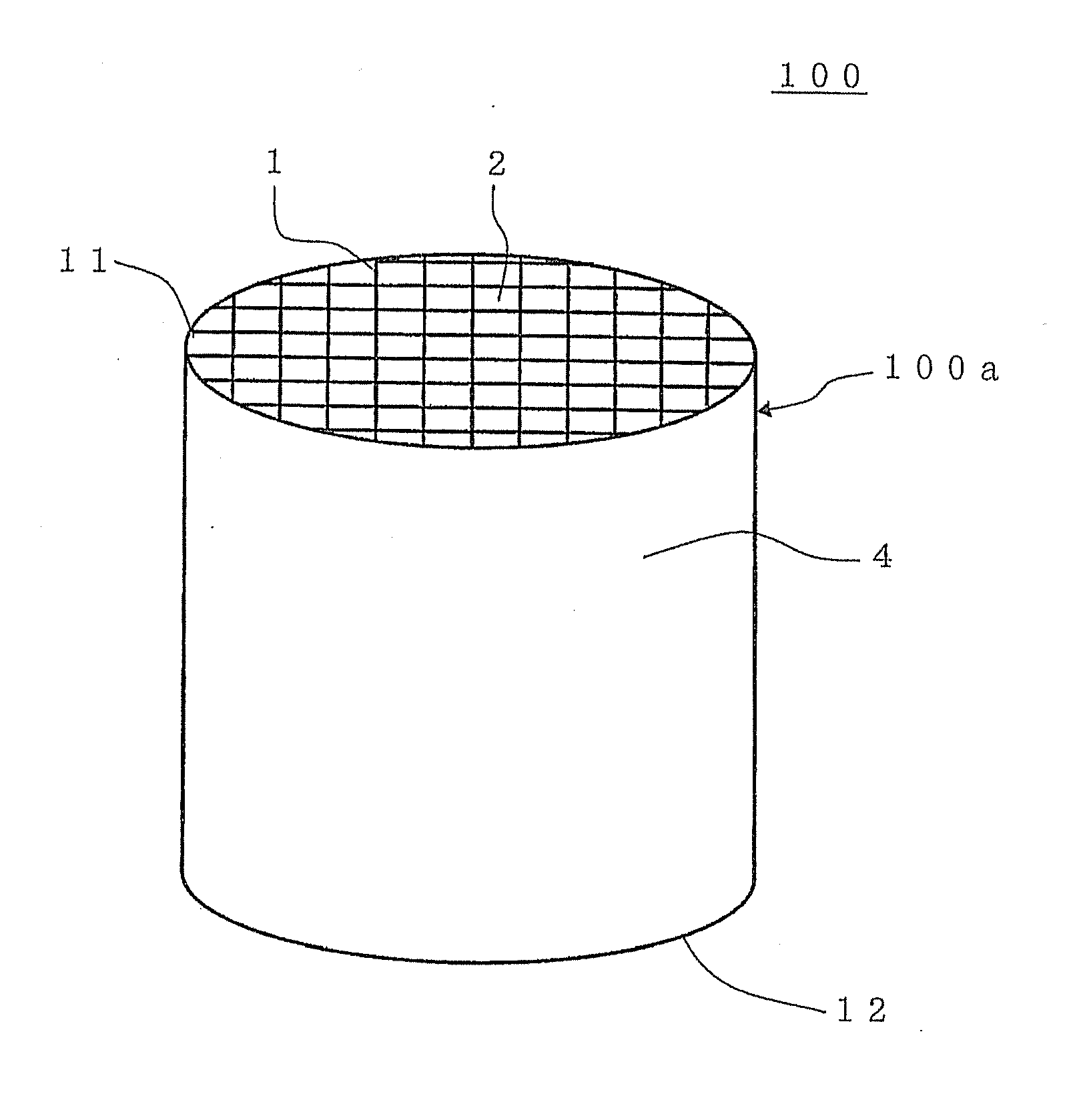
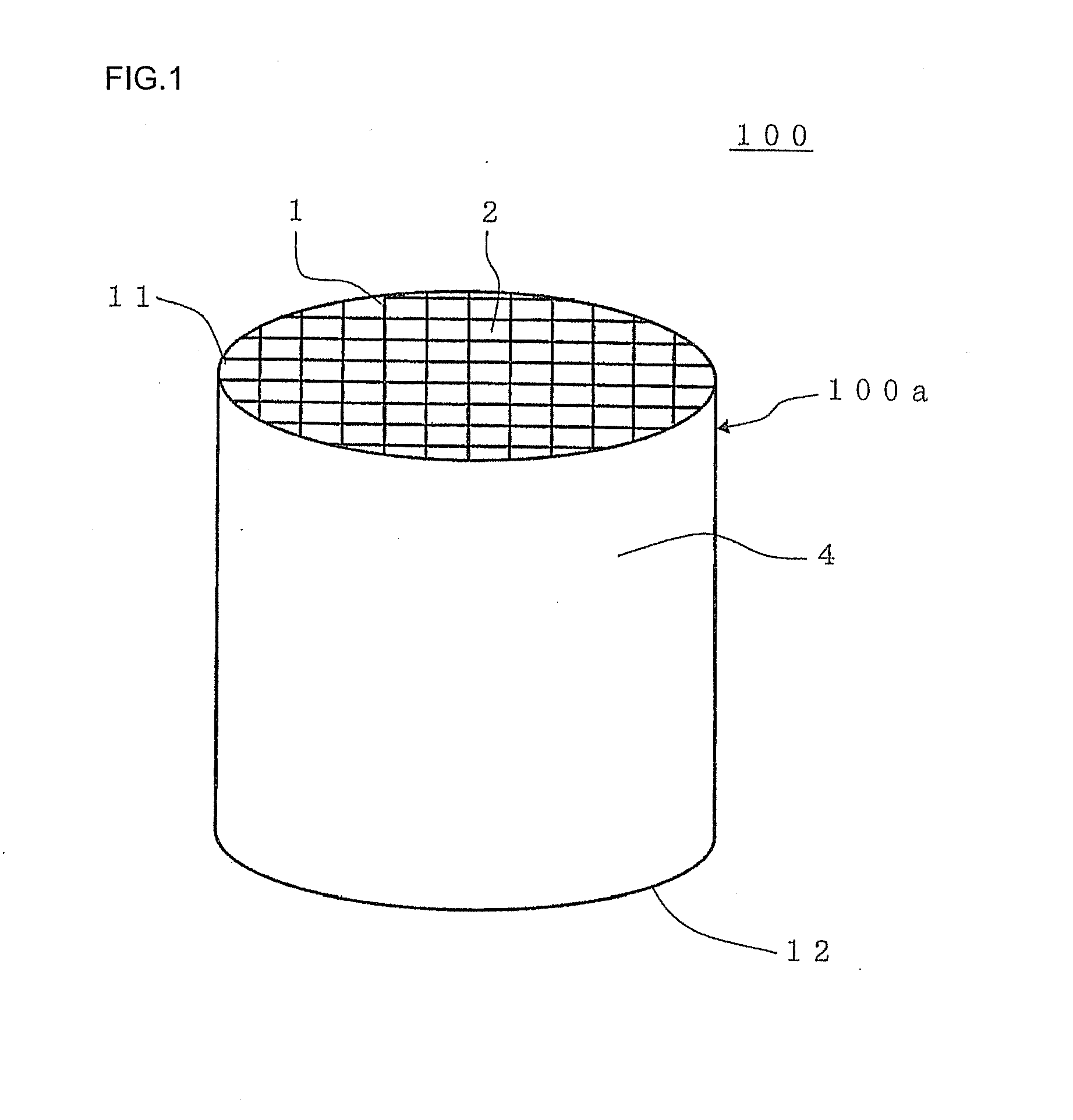
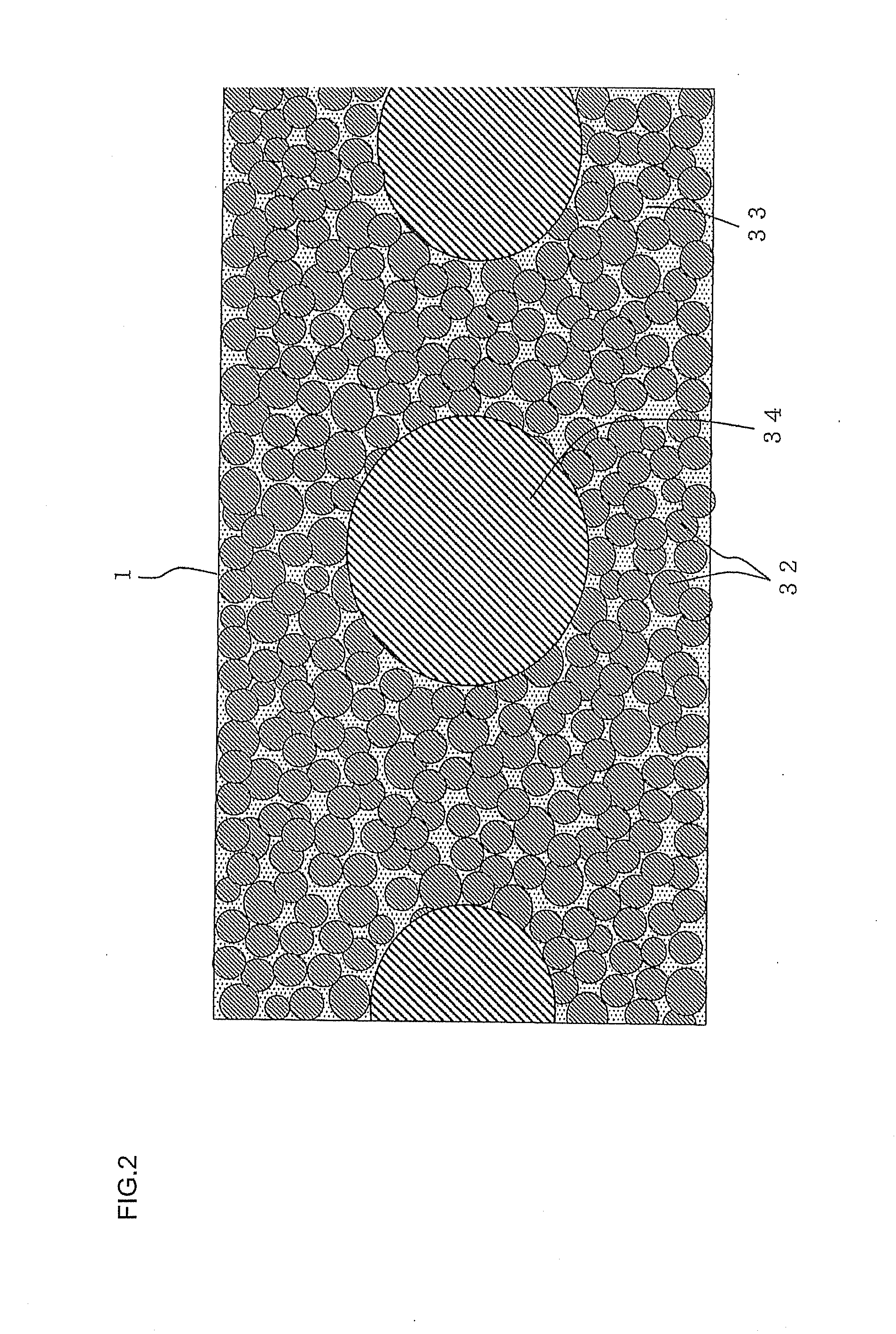
[0028]A zeolite honeycomb structure of the present invention is formed by extruding a raw material including predetermined amounts (predetermined volumes) of zeolite particles and noble metal loaded catalyst carriers, respectively. The noble metal loaded catalyst carriers have an average particle diameter which is ten or more times an average particle diameter of the zeolite particles, and a predetermined amount of a noble metal is loaded onto the noble metal loaded catalyst carriers. The zeolite honeycomb structure has a low pressure loss and an excellent NOx gas purification performance. In particular, since the zeolite honeycomb structure of the present invention is obtained by the extrusion forming, the above zeolite particles are arranged in a concentrated manner on a surface portion of partition walls disposed to form cells, and the above noble metal loaded catalyst carriers having a large average particle diameter are arranged inside the partition walls, whereby it is possible to effectively prevent ammonia necessary for purification of an NOx gas from being unnecessarily oxidized by the noble metal loaded catalyst carriers. Moreover, when a large amount of NO is included in the NOx gas, an excessive amount of NO can be oxidized into NO2 by the noble metal loaded catalyst carriers, and a catalyst reaction, which advantageously proceeds at a comparatively low temperature, can efficiently proceed. Furthermore, a catalyst carrier having a honeycomb shape is not required, but the zeolite particles and the noble metal loaded catalyst carriers form a structure in which particles are bound to one another with the inorganic binding material. In consequence, as compared with a honeycomb structure using a conventional ceramic carrier, a pressure loss can be lowered.
[0029]Furthermore, when a formed article is obtained by extrusion forming and is further fired, it is possible to manufacture a zeolite honeycomb structure in which the zeolite particles and the noble metal loaded catalyst carriers are arranged at predetermined positions. In consequence, manufacturing steps are remarkably simple.
[0031]In consequence, since the zeolite honeycomb structure of the present invention is a structure constituted of the formed article obtained by the extrusion forming, whereby the surface portions of the partition walls disposed to form the cells is constituted of the zeolite particles, and the noble metal loaded catalyst carrier is disposed inside the partition walls to cover the carrier with the zeolite particles. In consequence, when the zeolite honeycomb structure is used as a selective reduction type catalyst including ammonia (NH3) as a reducer, an excessive amount of ammonia, which cannot completely be adsorbed by the zeolite particles in the surface portions of the partition walls, can be oxidized by the noble metal loaded catalyst carriers inside the partition walls. Moreover, in an NOx reducing reaction which proceeds at a lower temperature as in the above reaction formula (1), when the amount of NO2 is inadequate, an excessive amount of NO is oxidized into NO2 by the noble metal loaded catalyst carriers inside the partition walls, whereby the reducing reaction of NOx can satisfactorily proceed in the surface portions of the partition wall again.

Problems solved by technology

However, a selective reduction type catalyst disclosed in Patent Document 1 is a catalyst loaded onto and used in an integral structure type carrier made of cordierite or the like, and this integral structure type carrier does not contribute to an NOx gas purifying function.
The presence of the carrier causes a problem that a pressure loss increases.
Moreover, in the catalyst disclosed in Patent Document 2, there are mixed zeolite particles onto which a noble metal is loaded and zeolite particles onto which copper is loaded, and the respective types of particles have the same degree of size, which causes a problem that owing to the presence of the zeolite particles including the noble metal loaded onto the surface of the catalyst, ammonia necessary for purification of the NOx gas is oxidized before ammonia exerts a function of a reducer.
Furthermore, in a honeycomb structure disclosed in Patent Document 3, after forming the honeycomb structure by use of inorganic particles containing a noble metal, the surfaces of the cell walls are coated with zeolite again, which causes a problem that manufacturing steps become remarkably complicated.
Moreover, it is remarkably difficult to regulate a film thickness of a zeolite film which coats the surfaces of the partition walls.
On the other hand, if the zeolite film is excessively thick, the problem of the increase of the pressure loss occurs.

Method used


Image

  • Zeolite honeycomb structure
  • Zeolite honeycomb structure
  • Zeolite honeycomb structure

Examples


example 1

[0144]As zeolite particles, there were prepared powder of zeolite particles made of β-type zeolite, subjected to 3 mass % ion exchange between cations of zeolite and iron ions and having an average particle diameter of 0.7 μm (hereinafter referred to as “the zeolite particles (1)”; and noble metal loaded catalyst carriers prepared by the following method and having an average particle diameter of 53 μm (hereinafter referred to as “the noble metal loaded catalyst carriers (1)”).

[0145](Preparation of Noble Metal Loaded Catalyst Carriers)

[0146]To 400 g of zeolite particles made of β-type zeolite, subjected to 3 mass % ion exchange between cations of zeolite and iron ions and having an average particle diameter of 0.7 μm, 6000 g of ceria sol containing 15 mass % of CeO2, 2000 g of alumina sol containing 20 mass % of Al2O3, and 400 g of platinum chloride aqueous solution containing 10 mass % of Pt were mixed. Then, the materials were further mixed by using a ball mill while adding water ...

example 2

[0163]A zeolite honeycomb structure was manufactured, purification performance was evaluated, and NH3 desorption ratio was measured in the same manner as in Example 1 except that as shown in Table 1 and Table 2, noble metal loaded catalyst carriers having an average particle diameter of 14 μm were used(hereinafter referred to as “the noble metal loaded catalyst carriers (2)”).

example 3

[0164]A zeolite honeycomb structure was manufactured, purification performance was evaluated, and NH3 desorption ratio was measured in the same manner as in Example 1 except that as shown in Table 1 and Table 2, noble metal loaded catalyst carriers were prepared by using 1500 g of a platinum chloride aqueous solution, and 400 g of the noble metal loaded catalyst carriers having an average particle diameter of 48 μm were used(hereinafter, referred to as “the noble metal loaded catalyst carriers (4)”).


PUM

PropertyMeasurementUnit
sizeaaaaaaaaaa
particle diametersaaaaaaaaaa
particle diameteraaaaaaaaaa

Abstract

The zeolite honeycomb structure is constituted of a zeolite raw material containing zeolite particles 32, noble metal loaded catalyst carriers 34 containing a noble metal loaded onto catalyst carriers, and an inorganic binding material 33 in a honeycomb shape. An average particle diameter of the noble metal loaded catalyst carriers 34 is ten or more times an average particle diameter of the zeolite particles 32. Moreover, the noble metal loaded catalyst carriers are contained in an amount corresponding to a volume ratio which is from 5 to 25 vol % with respect to 100 vol % of the zeolite particles, and the noble metal is loaded onto the noble metal loaded catalyst carriers in an amount corresponding to a mass ratio which is from 0.2 to 2.0 mass % with respect to 100 mass % of the zeolite particles in the zeolite honeycomb structure 100.

Description

BACKGROUND OF THE INVENTION[0001]1. Field of the Invention[0002]The present invention relates to a zeolite honeycomb structure. More particularly, it relates to a zeolite honeycomb structure having a low pressure loss and an excellent NOx purification performance.[0003]2. Description of the Related Art[0004]It is known that zeolite is a type of silicate having a mesh crystal structure provided with fine pores having a uniform diameter, there are present various chemical compositions represented by the general formula: WmZnO2n.sH2O (W: sodium, potassium, calcium or the like, Z: silicon, aluminum or the like, and s takes various values), and there are present many kinds (types) of crystal structures having different pore shapes'. Zeolite has an inherent adsorption ability, catalyst performance, solid acid characteristics, ion exchange ability and the like based on the respective chemical compositions or crystal structures, and is utilized in various use applications such as an adsorbi...

Claims


Application Information

Patent Timeline
Patent Type & Authority Applications(United States)
IPC IPC(8): B01J29/068B01J35/04
CPCB01D53/9418Y10T428/24149B01D2255/1021B01D2255/2065B01D2255/20738B01D2255/2092B01D2255/502B01D2255/92B01D2255/9202B01J23/40B01J29/40B01J29/7007B01J35/04B01J37/0009C04B38/0006C04B2111/0081F01N3/2828B01D2251/2062C04B35/18C04B38/0009B01J35/56
Inventor KIKUCHI, YOSHIO
Owner NGK INSULATORS LTD
Learn More