

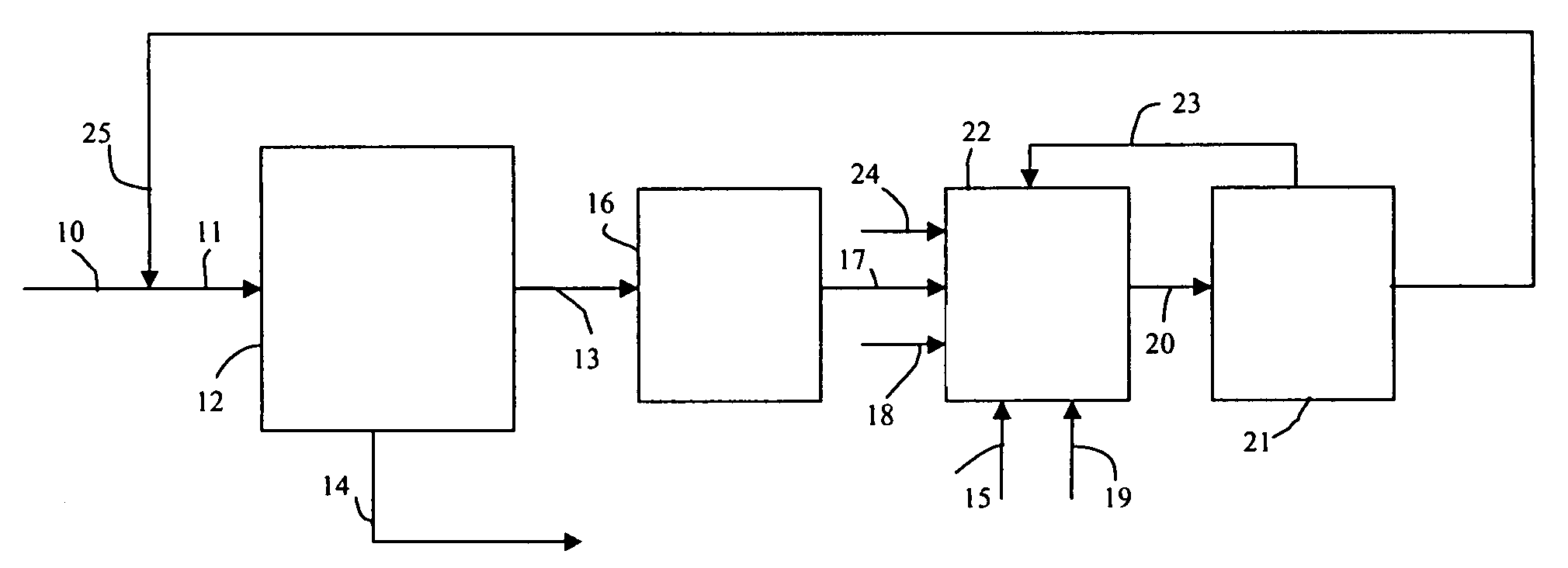
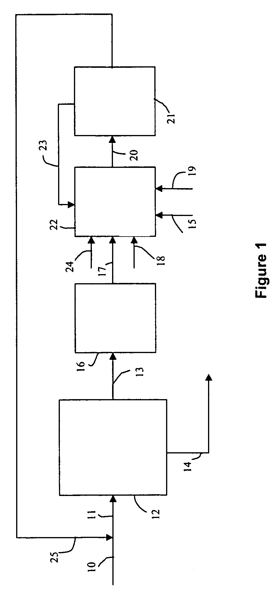
Series of hydroconversion and steam reforming processes to optimize hydrogen production on production fields
a technology of hydroconversion and steam reforming, which is applied in the direction of hydrocarbon oil cracking process, naphtha treatment, effluent separation, etc., can solve the problems of reducing the final yield of the complex, requiring a great deal of investment, and not only requiring investment, so as to increase the efficiency of the ensemble
- Summary
- Abstract
- Description
- Claims
- Application Information
AI Technical Summary
Benefits of technology
Problems solved by technology
Method used
Image

Examples
example 1
Unit Functioning at 60% Conversion of 540° C.+
[0072]Heavy vacuum residue (VR) from the Persian Gulf was treated. The density at 15° C. was 1.048. All yields were calculated on the basis of 100 (by weight) of VR.
[0073]This Safaniya vacuum residue was treated in a pilot unit comprising two reactors in series functioning as ebullated beds. The total volume of each reactor was 2.24 litres.
[0074]This pilot unit simulated an industrial ebullated bed vacuum residue H-Oil® unit. The fluids were in upflow mode in this reactor, as in an industrial unit. Internal recycling of the liquid allowed the catalyst to be ebullated in the reactor.
[0075]The operating conditions were as follows:[0076]feed flow rate: 1.4 l / h;[0077]total pressure: 156 bars absolute;[0078]hydrogen flow rate: 840 l / h (i.e. about 13 l / h under conditions);[0079]temperature in reactors: 410° C.;[0080]flow rate of liquid recycled to reactor: 30 l / h.
[0081]The results below are expressed as the percentage by weight with respect to...
example 2
Unit Functioning at 90% Conversion of 540° C.+
[0089]The fuel gas from the hydroconversion unit represented, at this degree of conversion, 9.5% by weight of the fresh feed to the hydroconversion unit. Said fuel gas contained hydrogen which is used during conversion of sulphur-containing compounds (and their capture) upstream of the pre-reformer and reformer. A very small quantity of natural gas was added.
[0090]The composition of the gas mixture sent to the pre-reformer (purified fuel gas+natural gas+steam) was as follows (mol %):
[0091]
Methane6.7%Ethane2.9%Propane2.6%Butane1.7%Steam77.9%Hydrogen8.2%TOTAL100.0%
[0092]The quantity of steam introduced before the pre-reformer was such that the H2O / C mole ratio before the reforming furnace was at least 3.1. The pressure in the steam reforming unit was 30 bars absolute.
[0093]The composition of the gas at the pre reformer outlet was as follows (the reactions took place at 550° C.):
[0094]
Methane20.0%EthanetracesPropanetracesButanetracesSteam62...
example 3
Unit Functioning at 95% Conversion of 540° C.+
[0099]The fuel gas from the hydroconversion unit represented 11.8% by weight of the fresh feed at this degree of conversion. Said fuel gas contained hydrogen which was used during the conversion of sulphur-containing compounds (and their capture) upstream of the pre-reformer and the reformer.
[0100]The composition of the mixture of gas sent to the pre-reformer (purified fuel gas+steam) was as follows (mol %):
[0101]
Methane6.2%Ethane2.9%Propane2.7%Butane1.7%Steam78.1%Hydrogen8.4%TOTAL100.0%
[0102]The quantity of steam introduced before the pre-reformer was such that the mole ratio H2O / C before the reforming furnace was at least 3.1. The pressure at the unit inlet was 30 bars absolute.
[0103]The composition of the gas at the pre-reformer outlet (the reactions occurred at 550° C.) was as follows (mol %):
[0104]
Methane20.0%EthanetracesPropanetracesButanetracesSteam62.2%Hydrogen13.5%CO24.3%TOTAL100.0%
[0105]The gas was then introduced to the reform...
PUM
| Property | Measurement | Unit |
|---|---|---|
| temperature | aaaaa | aaaaa |
| partial pressure | aaaaa | aaaaa |
| total pressure | aaaaa | aaaaa |
Abstract
Description
Claims
Application Information