Electroconductive 12CaO—7Al2O3 and compound of same type, and method for preparation thereof

a technology of electroconductive and compound, applied in the field of electroconductive 12cao—7al2o3 and compound of same type, can solve the problems of high reactivity of compound with moisture, chemical instability, etc., and achieve the effect of strong reducing

Active Publication Date: 2009-03-24
JAPAN SCI & TECH CORP
View PDF9 Cites 12 Cited by
  • Summary
  • Abstract
  • Description
  • Claims
  • Application Information

AI Technical Summary

Problems solved by technology

Subsequently, several organic electrides were discovered; however, these compounds are stable only at a low temperature, such as approximately 100 K or less, and are considerably unstable materials so as to react with air and / or water.
However, this compound has also high reactivity with moisture and is chemically unstable (Non-Patent Document 5).
In addition, a diode has also been proposed that uses superior electron emission properties of an electride compound (Patent Document 8); however, since the electride compounds that have been obtained as of today are unstable from thermal and chemical points of view, the proposed vacuum diode can only be operated at a low temperature.Patent Document 1 Japanese Patent Application No. 2001-49524 (Japanese Unexamined Patent Application Publication No. 2002-3218)Patent Document 2 Japanese Patent Application No. 2001-226843 (Japanese Unexamined Patent Application Publication No. 2003-40697)Patent Document 3 Japanese Patent Application No. 2001-377293Patent Document 4 Japanese Patent Application No. 2001-117546 (Japanese Unexamined Patent Application Publication No. 2002-316867)Patent Document 5 Japanese Patent Application No. 2002-117314Patent Document 6 Japanese Patent Application No. 2002-045302 (Japanese Unexamined Patent Application Publication No. 2003-238149)Patent Document 7 Japanese Patent Application No. 2002-188561Patent Document 8 U.S. Pat. No. 5,675,972 Specification and DrawingsNon-Patent Document 1 H. B. Bartl and T. Scheller, Neuses Jarhrb.

Method used


Image

  • Electroconductive 12CaO—7Al2O3 and compound of same type, and method for preparation thereof
  • Electroconductive 12CaO—7Al2O3 and compound of same type, and method for preparation thereof
  • Electroconductive 12CaO—7Al2O3 and compound of same type, and method for preparation thereof

Examples


example 1

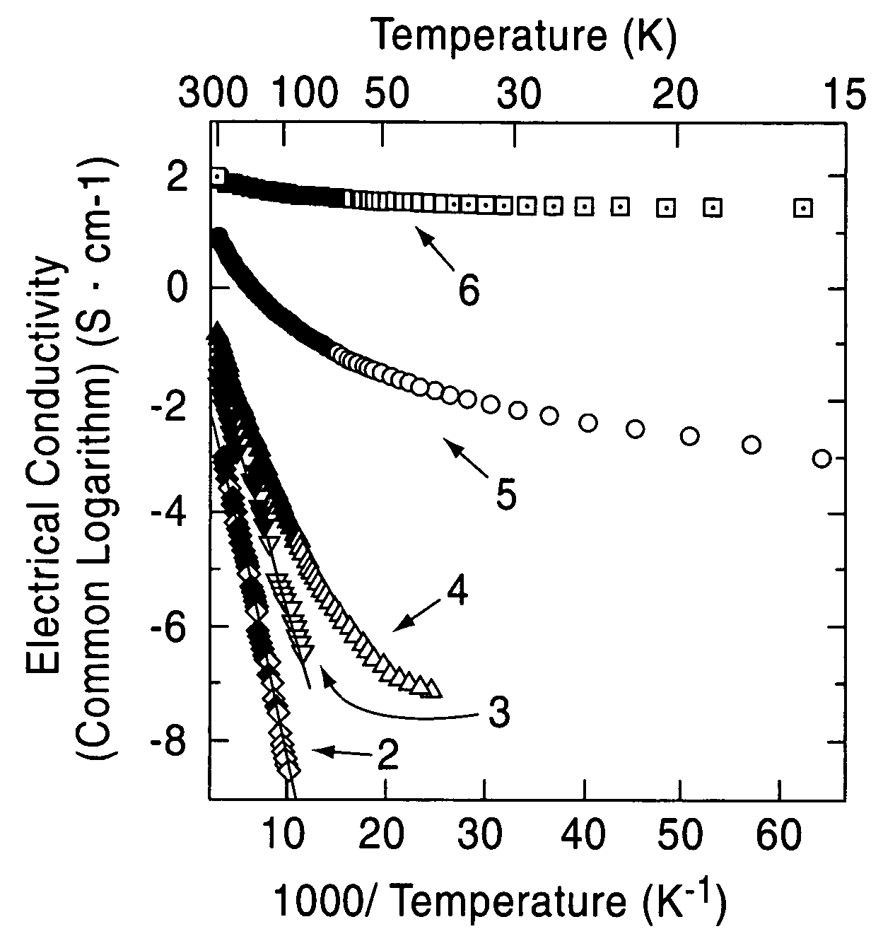
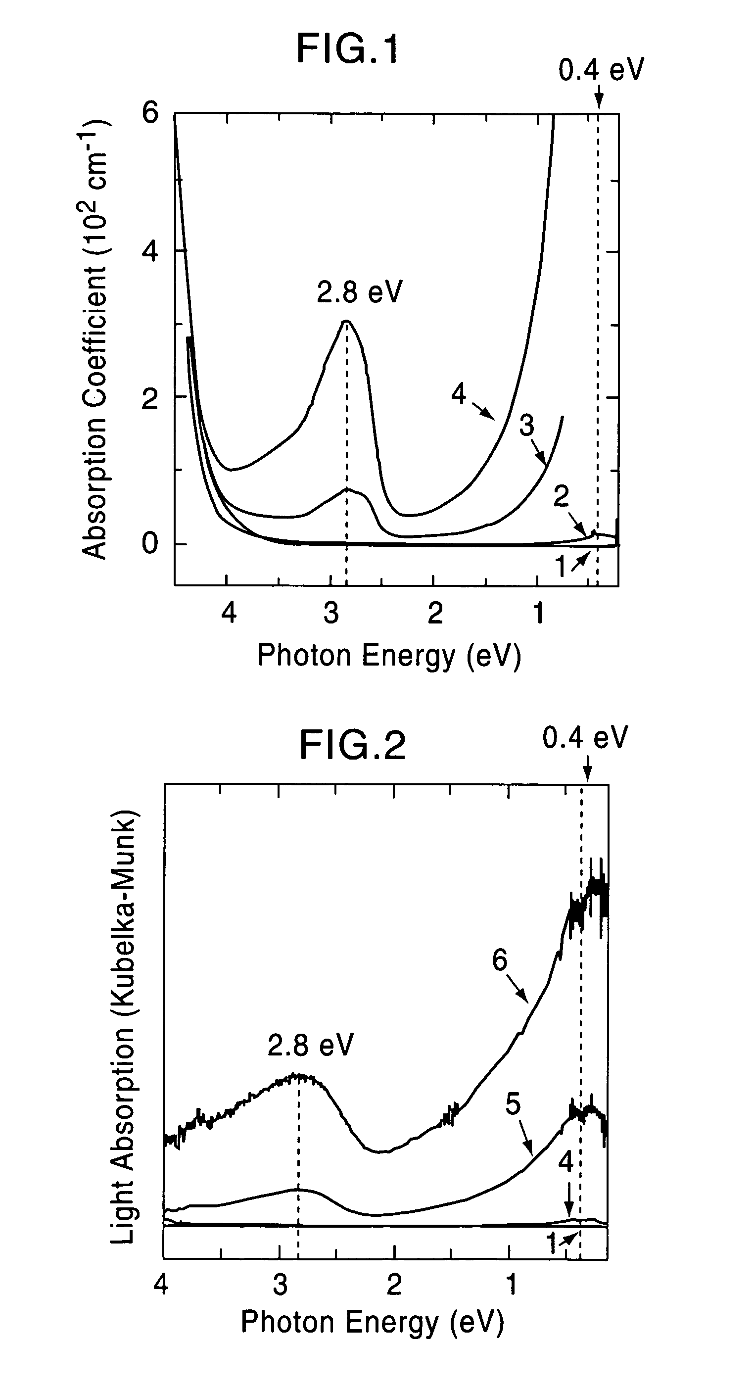
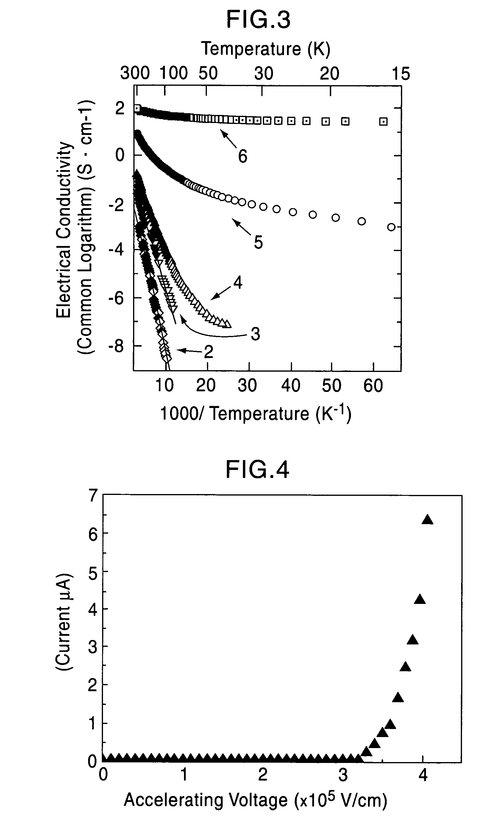
[0075]A single crystal C12A7 compound formed by a floating zone method (FZ method) was processed into a thin plate having a size of 0.4 mm×4 mm×7 mm, and two surfaces thereof were mirror polished (sample 1). This single crystal thin plate and a calcium metal piece were placed in a quartz tube, and the tube was then vacuum sealed. Five of the samples were maintained at 700° C. for different times, that is, 4, 12, 18, 40, and 240 hours (the crystal thin plates processed for different times are called sample 2, 3, 4, 5, and 6, respectively). As the holding time was increased, the C12A7 single crystal thin plates were sequentially colored in yellow, green, and black in that order; however, the surface layers were each transparent, and from an x-ray diffraction spectrum, it was confirmed that the surface layer is calcium oxide. It was understood from an x-ray diffraction pattern that a crystal thin plate obtained by removing the calcium oxide layer retains the crystal structure of C12A7....

example 2

[0079]After a fine powder of a C12A7 compound was molded by a uniaxial press under a pressure of 300 kg / cm2, additional molding was performed by a hydrostatic pressure press under a pressure of 2,000 kg / cm2. After two of the molded bodies thus formed were placed in respective carbon crucibles each capped with a lid, the crucibles were further placed in respective alumina crucibles, and heating was then performed at a temperature increasing rate of 400° C. / hour to 1,550° C. for one crucible and to 1,600° C. for the other crucible. Subsequently, the crucibles were held at the above respective temperatures where the molded bodies are melted for 1 hour and were then cooled to room temperature at a temperature decrease rate of 400° C. / hour for the solidification.

[0080]The solid materials thus obtained were dense and had black green color, and the degree of blackness of the solid material held at 1,600° C. was higher than that of the solid material held at 1,550° C. The electrical conduct...

example 3

[0084]A C12A7 thin film deposited on a MgO substrate was maintained at 600° C. and was implanted with Ar+ ions accelerated at approximately 360 kV. The thin film before ion implantation showed insulating properties; however, when Ar+ ions were implanted at a dose of 5×10¹⁷ / cm2, an electrical conductivity of approximately 1 S / cm was obtained. From a Rutherford backscattering spectrum, it was confirmed that Ar+ ions are not contained in the film.

[0085]Accordingly, it is believed that after Ar+ ions collide with the free oxygen ions, the free oxygen ions are kicked out of the film by a knock-on effect, and as a result, in order to maintain the charge neutrality, electrons are allowed to remain in the film. That is, by implanting Ar+ ions into a C12A7 thin film at high temperature, electrons are substituted for free the oxygen ions, and as a result, electrical conductivity can be realized.


PUM

PropertyMeasurementUnit
electrical conductivityaaaaaaaaaa
temperatureaaaaaaaaaa

Abstract

In a solid solution system of Al2O3 and CAO or SrO, it has been difficult to obtain a material having a high electrical conductivity (>10−4 S·cm−) at room temperature.A compound is provided in which electrons at a high concentration are introduced into a 12CaO.7Al2O3 compound, a 12SrO.7Al2O3 compound, or a mixed crystal compound containing 12CaO.7Al2O3 and 12SrO.7Al2O3. The compound formed by substituting all the free oxygen ions with electrons is regarded as an electride compound in which [Ca24Al28O64]4+(4e−) or [Sr24Al28O64]4+(4e−) serves as a cation and electrons serve as anions. When a single crystal or a hydrostatic pressure press molded material of a fine powder thereof is held at approximately 700° C. in an alkaline metal vapor or an alkaline earth metal vapor, melt of a hydrostatic pressure press molded material of a powder is held at approximately 1,600° C. in a carbon crucible, followed by slow cooling for solidification, or a thin film of the compound held at approximately 600° C. is implanted with rare gas ions, a great number of the free oxygen ions can be substituted with electrons.

Description

TECHNICAL FIELD[0001]The present invention relates to a 12CaO·7Al2O3 (hereinafter referred to as “C12A7”) compound, a 12SrO·7Al2O3 compound (hereinafter referred to as “S12A7”), or a mixed crystal compound containing of 12CaO·7Al2O3 and 12SrO·7Al2O3, the compounds each containing electrons at a high concentration, to methods for manufacturing the above compounds, and to application thereof.BACKGROUND ART[0002]In 1970, H. B. Bartl et al. disclosed a very unique characteristic of a 12A7 crystal in which 2 oxygen atoms out of 66 oxygen atoms in a unit cell containing 2 molecules are clathrated in the form of “free oxygen” in space of cages present in the crystal (Non-Patent Document 1). Subsequently, it has also been disclosed that the free oxygen can be substituted with various types of anions.[0003]Hosono, one of the inventors of the present invention, discovered that O2− at a concentration of approximately 1×1019 cm−3 is clathrated by measuring electron spin resonance of a C12A7 cry...

Claims


Application Information

Patent Timeline
Patent Type & Authority Patents(United States)
IPC IPC(8): C30B1/10C01F7/164C01F7/166C04B35/44H01B1/08
CPCC01F7/164C01F7/166C04B35/44C04B35/653H01B1/08C01P2006/40C04B2235/3208C04B2235/3213C04B2235/604C04B2235/6587C04B2235/664C04B2235/787C04B2235/94
Inventor HOSONO, HIDEOHIRANO, MASAHIROHAYASHI, KATSUROMIYAKAWA, MASASHITANAKA, ISAO
Owner JAPAN SCI & TECH CORP
Why Eureka
Try Eureka