Apparatus and methods for simultaneous operation of miniaturized reactors

a technology of reactors and apparatus, applied in the field of apparatus and methods for simultaneous operation of miniaturized reactors, can solve the problems of limiting the volume of bench-scale bioreactors, unable to keep pace with the current rate of biological system discovery and genetic manipulation, and unable to carry out large numbers of experiments quickly and efficiently

Inactive Publication Date: 2009-03-24
MASSACHUSETTS INST OF TECH
View PDF6 Cites 51 Cited by
  • Summary
  • Abstract
  • Description
  • Claims
  • Application Information

AI Technical Summary

Problems solved by technology

One significant challenge is to carry out large numbers of experiments rapidly and efficiently.
Bioprocess development techniques have been unable to keep pace with the current rate of discovery and genetic manipulation in biological systems.
Bench-scale bioreactors, with typical volumes of between 2 and 10 liters, are limiting for a number of reasons including the time required to obtain sufficient data for a biological system, the effort required to obtain the data, and the high cost of these systems.

Method used


Image

  • Apparatus and methods for simultaneous operation of miniaturized reactors
  • Apparatus and methods for simultaneous operation of miniaturized reactors
  • Apparatus and methods for simultaneous operation of miniaturized reactors

Examples


example 1

Fabrication of a Microscale Bioreactor

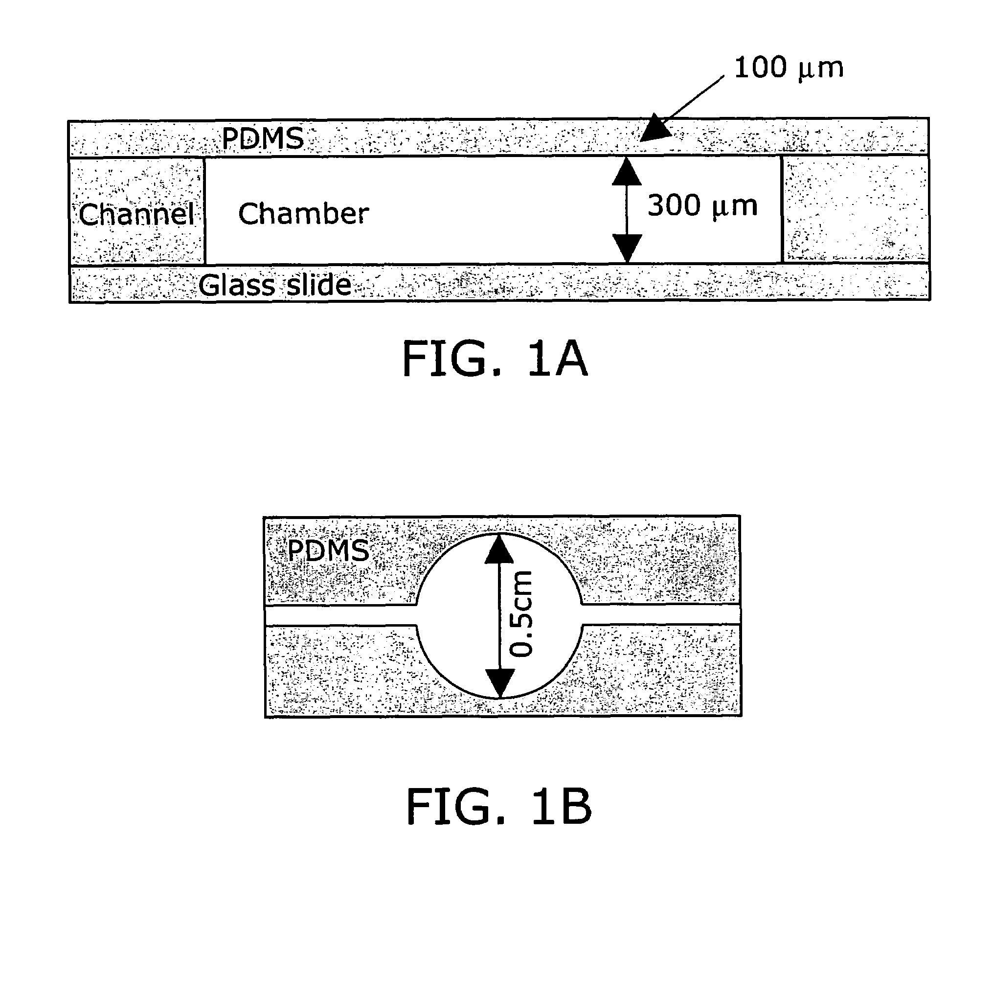
[0246]Poly(dimethylsiloxane) (PDMS) was selected as the microfermentor fabrication material in part because of its biocompatibility and optical transparency in the visible range. The high gas permeability of this material also allows it to be used as the material for an aeration membrane. Glass was selected as the microfermentor base for its transparency and rigidity.

[0247]The fabrication procedure used is depicted in FIG. 10. Fabrication of the microfermentor was carried out using soft lithography as described in (58). In the first step of the fabrication process photolithography was used to fabricate a negative master out of silicon and the photo-definable epoxy SU-8. The body of the microfermentor was then cast in PDMS by squeezing the liquid polymer between the negative master and a piece of cured and passivated (silanized) PDMS. The aeration membrane was made by spin-coating the liquid polymer onto a blank wafer. The body and the membrane w...

example 2

Modeling Aeration Within a Microscale Bioreactor

[0248]Modeling of oxygen diffusion into the microfermentor was carried out using a one-dimensional resistance-in-series model of the membrane and the medium, taking oxygen consumption to be a zeroth-order reaction term (constant oxygen consumption / viable cell). For calculations at 35° C., an oxygen diffusivity in PDMS of 3.4×10⁻⁵ cm2 / s and a solubility of 0.18 cm3 (STP) / cm3 / atm were assumed (44). For oxygen in water a diffusivity of 2.5×10⁻⁵ cm2 / s and a solubility of 7 mg / l were used (45), and it is assumed that values for culture medium would be approximately the same. A typical E. coli oxygen uptake rate (OUR) of 30 (mmol O2) / (gram dry cell weight / h) was assumed (46).

[0249]The models assumed a stagnant medium (no mixing). If some method of mixing is implemented, the maximum depth of the microfermentor will increase. The model assumes steady state conditions (see below for transient analysis of oxygen transport during growth). For the...

example 3

Setup of a Microscale Bioreactor System

[0266]FIG. 14 shows a schematic of a microscale bioreactor system with associated optical excitation and detection sources. Optical fibers transmit light to the bottom of the fermentor. Biomass is monitored by measuring the amount of light transmitted to the collecting lens above.

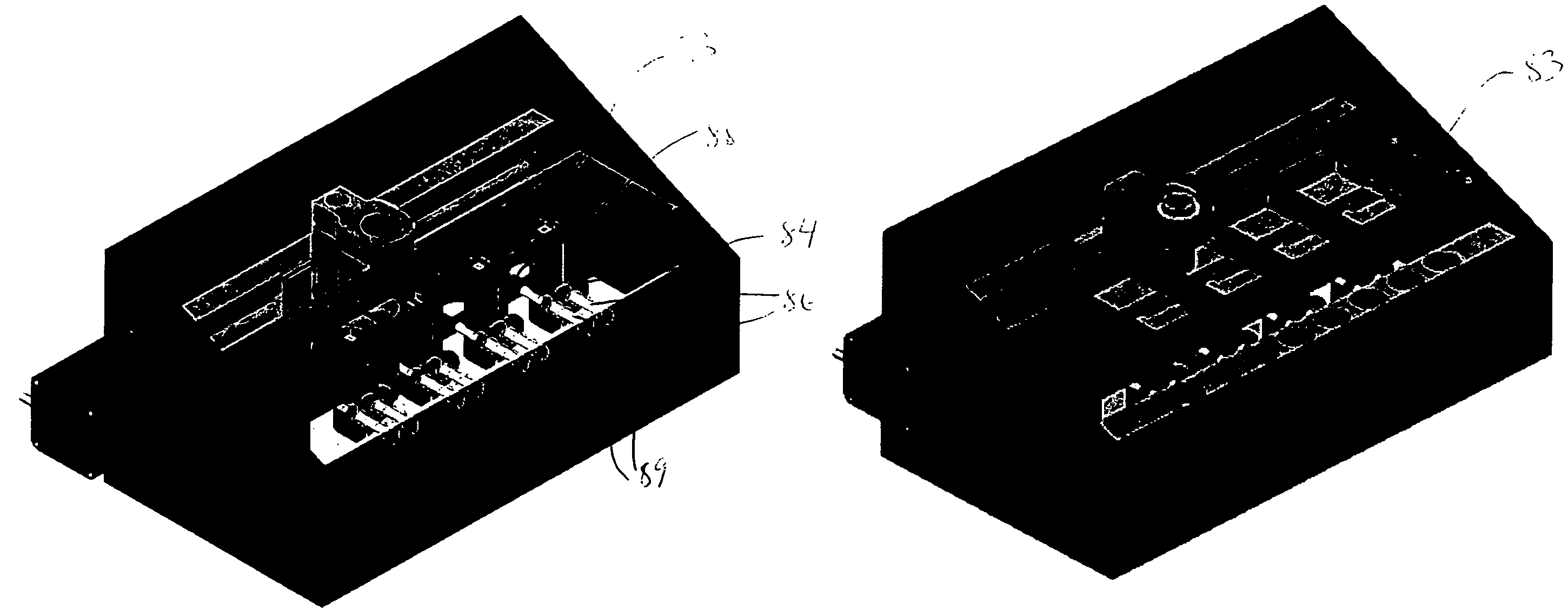
[0267]The microfermentor is placed in an enclosed chamber designed to facilitate environmental control during fermentations. The chamber is fabricated from aluminum and has a screw-on lid that can be sealed with an O-ring. FIG. 15A depicts the chamber with the microfermentor inside. FIG. 15B is a second view to more clearly show the microfermentor. (Note that the slide that forms the base of the microfermentor is transparent.) In this system, evaporation from the microfermentor is controlled by making the chamber airtight and by maintaining the air within the chamber at high humidity, e.g., 100% humidity. This is accomplished by placing open reservoirs of water beside ...


PUM

PropertyMeasurementUnit
volumesaaaaaaaaaa
volumesaaaaaaaaaa
volumesaaaaaaaaaa

Abstract

The present invention provides a variety of microscale bioreactors (microfermentors) and microscale bioreactor arrays for use in culturing cells. The microfermentors include a vessel for culturing cells and means for providing oxygen to the interior of the vessel at a concentration sufficient to support cell growth, e.g., growth of bacterial cells. Depending on the embodiment, the microfermentor vessel may have various interior volumes less than approximately 1 ml. The microfermentors may include an aeration membrane and optionally a variety of sensing devices. The invention further provides a chamber to contain the microfermentors and microfermentor arrays and to provide environmental control. Certain of the microfermentors include a second chamber that may be used, e.g., to provide oxygen, nutrients, pH control, etc., to the culture vessel and / or to remove metabolites, etc. Various methods of using the microfermentors, e.g., to select optimum cell strains or bioprocess parameters are provided. The invention provides microreactors having a variety of different designs, some of which incorporate active stirring and / or have the capability to operate in batch or fed-batch mode. The invention further provides an apparatus and methods for simultaneous operation of a plurality of microreactors, with monitoring of the individual microreactors during a run. The invention further provides methods of performing gene expression analysis on cells cultured in microreactors.

Description

CROSS-REFERENCE TO RELATED APPLICATION[0001]This application is a continuation-in-part of U.S. patent application Ser. No. 10 / 427,373 filed May 1, 2003, now abandoned, which is herein incorporated by reference; and claims priority to U.S. Provisional Patent Application 60 / 376,711, filed May 1, 2002.BACKGROUND OF THE INVENTION[0002]A critical driving force behind research in bioprocess science and engineering continues to be the demand for fast and accurate analytical information that can be used, for example, to evaluate the interactions between biological systems and bioprocess operations. One significant challenge is to carry out large numbers of experiments rapidly and efficiently. This issue is of particular importance since many of the advances in molecular biology now lead to large numbers of potential biological systems that contain evolved biocatalysts, new pathway designs, and a variety of unique biological organisms from diverse sources.[0003]Bioprocess development techniq...

Claims


Application Information

Patent Timeline
Patent Type & Authority Patents(United States)
IPC IPC(8): C12M1/12C12M1/00C12M1/34C12M3/00G06K9/00B01L3/00B01L9/00C12M1/36G01N35/00
CPCB01F13/0059B01F13/0827B01L3/5027B01L9/527C12M23/16C12M35/08C12M41/48B01J2219/00283B01J2219/00317B01J2219/00479B01J2219/00481B01J2219/00484B01J2219/00495B01J2219/00585B01J2219/00599B01J2219/00691B01J2219/00743B01L3/502715B01L3/502723B01L2300/0681B01L2300/0816B01L2300/0867B01L2300/0877B01L2300/10B01L2400/0466B01L2400/0487G01N2035/00326Y10S435/808Y10S435/809B01F33/30B01F33/453C12M1/12
Inventor BOCCAZZI, PAOLOCHEN, ANGELA Y.JENSEN, KLAVS F.SZITA, NICOLASZANZOTTO, ANDREAZHANG, ZHIYU
Owner MASSACHUSETTS INST OF TECH
Why Eureka
Try Eureka