Despite the importance of storage applications in networks, their usefulness has, until recently, been greatly limited by the insufficient bandwidth provided by networks.
The introduction of
gigabit and multi-
gigabit network technology, however, is changing the rules of the game.
At the same time, creating storage and network systems capable of adequately handling such amounts of information and usage loads is not a simple task.
The flip side is that file systems are complex and very
processing-intensive, which increases substantially the performance requirements to any computer that provides file services over a fast network.
To serve files to hundreds and thousands of users simultaneously requires tremendous amounts of
processing power, memory and
bus bandwidth.
The result of this approach is that high-end file servers are essentially massively
multiprocessing supercomputers, with all the associated costs and complexity.
However, high-performance
multiprocessing file servers quickly run into the performance limits of their storage subsystems.
Single-box solutions are subject to several serious problems.
First, because of the extremely
high complexity and the need to develop custom
silicon in order to satisfy performance requirements, single box solutions are very expensive.
Second, their development cycles are exceedingly long, virtually guaranteeing that they will be “behind the curve” in many important aspects, such as
software technologies, protocols, etc., by the time they are generally commercially available.
Since storage requirements effectively double every year or so, these boxes often become obsolete long before the customers manage to depreciate their high cost.
The main challenge in the above-mentioned
file system comes from the need to frequently synchronize and coordinate access to the storage among all members of the cluster.
These components quickly become a major
bottleneck that prevents the scaling of cluster file systems beyond about sixteen nodes.
Solutions that partially relieve this problem introduce other problems, including custom functionality in storage subsystems and specialized
client-side
software.
If any of these approaches is commercialized, the requirement for using proprietary storage subsystems will have substantial negative effect on both adoption and price, while the need to rely on proprietary client-side
software that has to be installed in every client accessing the
system make the
system fragile, prone to security breaches and hard to deploy and support.
Both single box solutions and cluster file systems are tightly coupled systems that exhibit serious
scalability limitations.
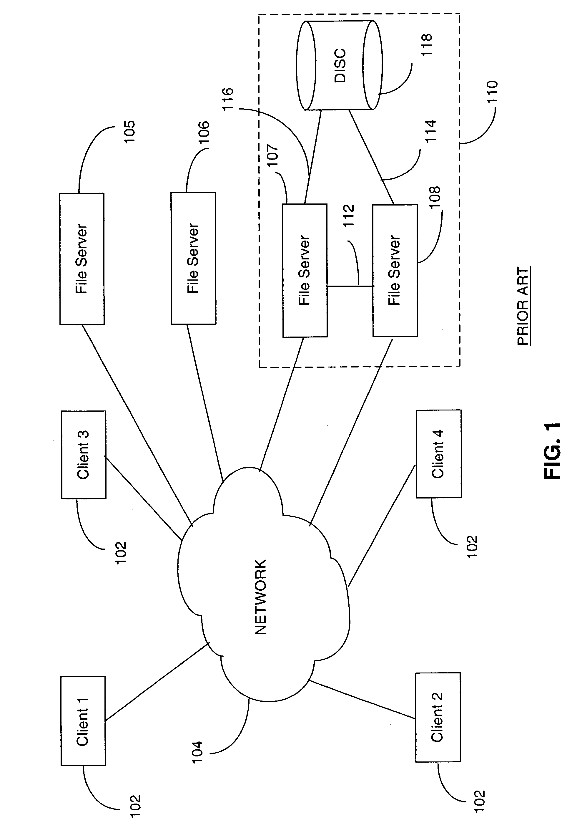
The main problem with available distributed file systems is that they do not scale in performance nearly as well as they scale in storage capacity.
Thus, the performance the
distributed file system can deliver to a single client (
workstation or
application server) is limited by the performance of the utilized individual file servers, which, considering the large number of servers involved, is not likely to be a very high performance
machine.
Another problem that has great
impact in commercial environments is the fact that most distributed file systems require specialized client-side software that has to be installed and configured properly on each and every client that is to access the file
system.
This tends to create massive versioning and support problems.
Moreover, distributed file systems are very prone to “hotspotting”.
Hotspotting occurs when the demand for an individual file or a small set of files residing on a
single server increases dramatically over short period of time, resulting in severe degradation of performance experienced by a large number of users.
Yet another problem with distributed file systems is in their low manageability.
Although most aspects of the distributed file systems can be managed while the system is on-line, the heterogeneous and distributed nature of these systems effectively precludes any serious
automation of the management tasks.
As a result, managing distributed file systems requires large amount of highly qualified labor.
Although many approaches to scaling network file systems have been taken over the last fifteen years, none has succeeded in delivering on the high performance, high
scalability and simple management promise of storage networking.
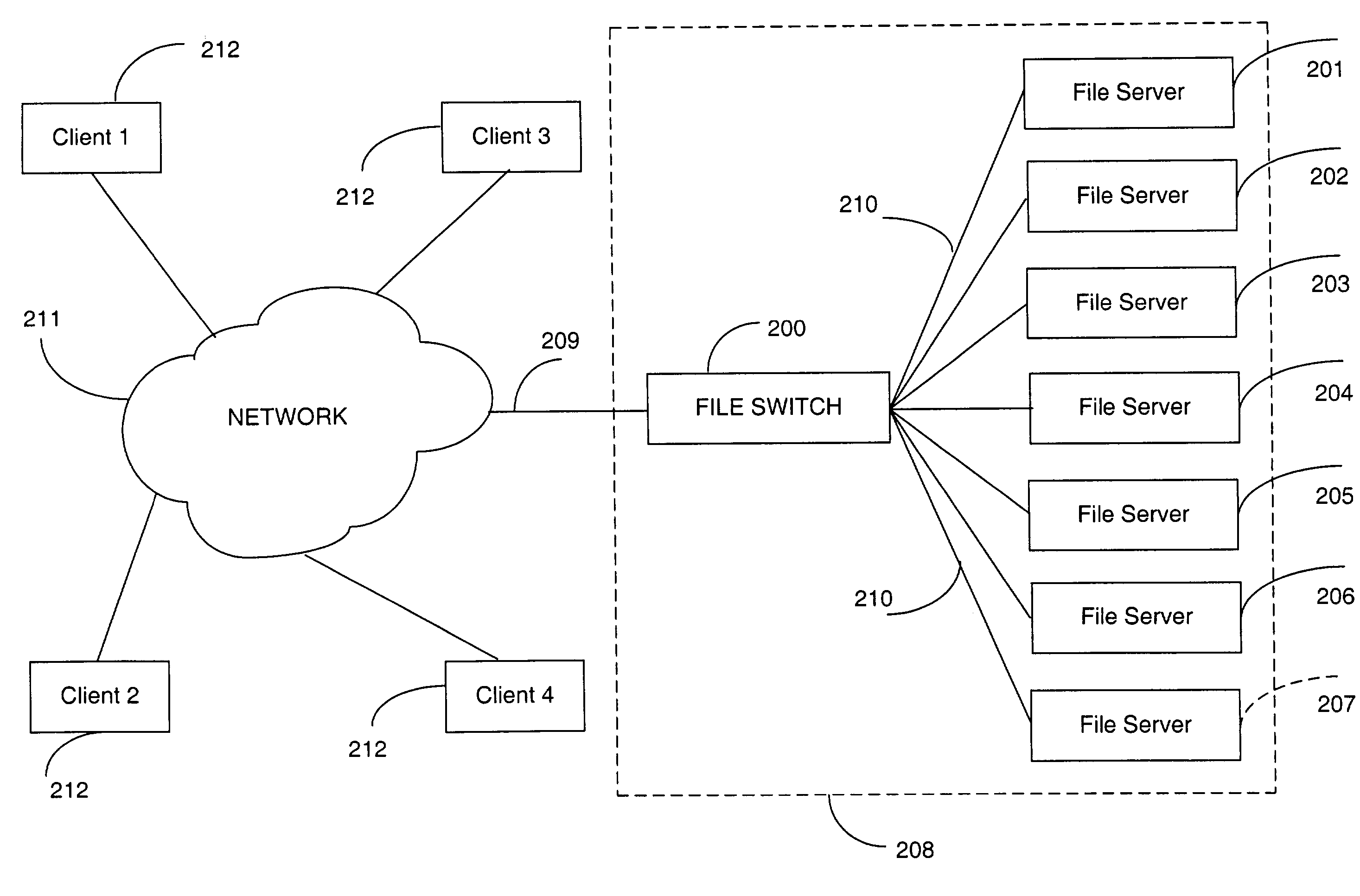
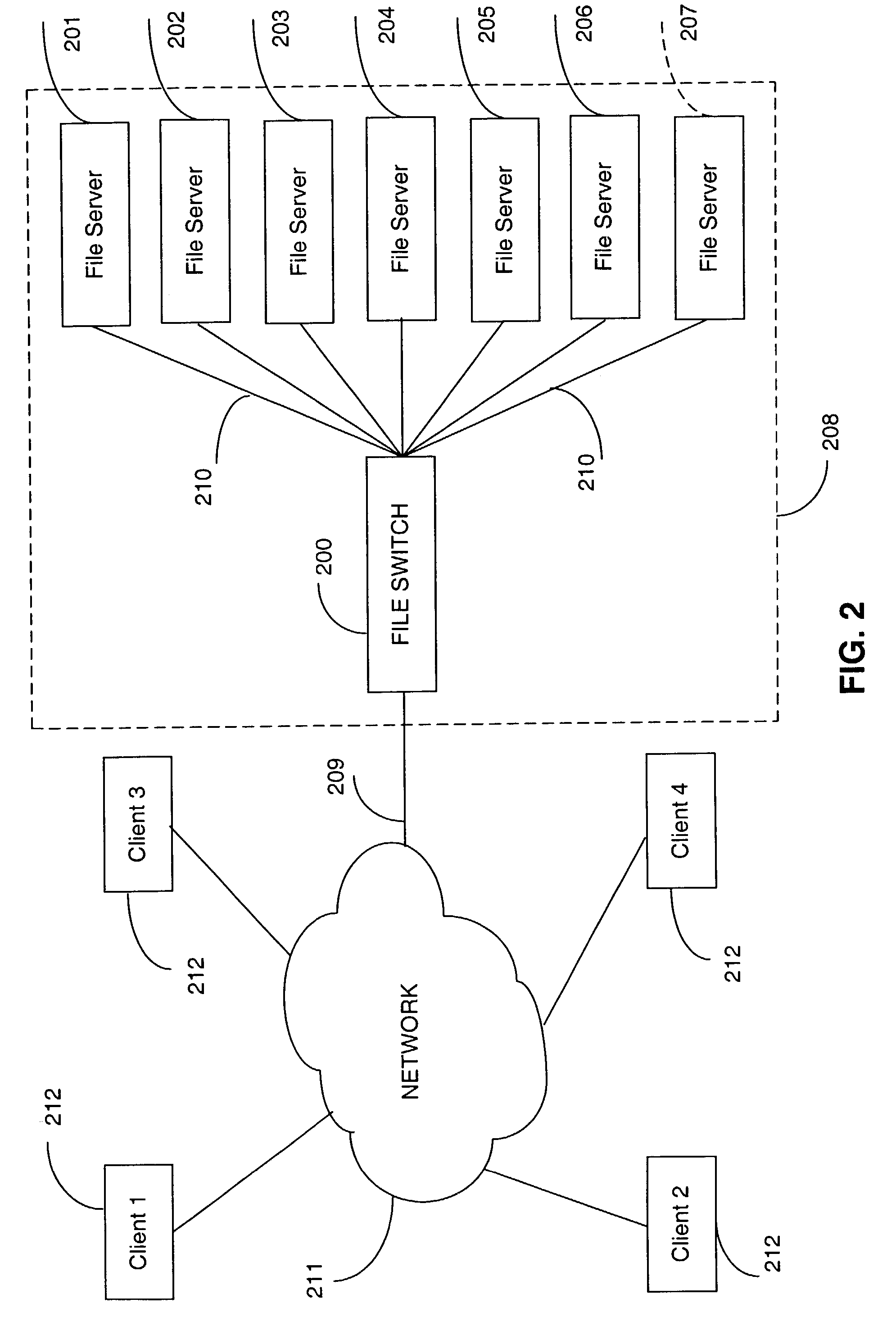
Analysis of the systems described above shows that all of their limitations can be traced to a small set of fundamental flaws, namely, all available systems suffer from at least one of the following problems:1. One file, one
server.
The inability to utilize multiple file servers in handling requests for a single file limits severely the
throughput available to any single client and does not allow the system to balance the load across all available
processing resources.2. Centralized arbitration and
metadata management.
The need to arbitrate access to storage and the shared data structures used to manage it creates a
bottleneck that severely limits the scalability of the system.3. Proprietary client-side software.
The need to buy, install, configure and support a non-trivial piece of software across all client machines running multiple different operating systems creates serious barrier for adoption.
However, there is no currently available system that can deliver all characteristics needed for storage networking to achieve its promise.

