Laser irradiation apparatus, method of laser irradiation, and method for manufacturing semiconductor device

a laser irradiation and laser irradiation technology, applied in the direction of photomechanical equipment, manufacturing tools, instruments, etc., can solve the problems of distortion in the outer edge, distortion may be generated in the shape, and the micromirror is not a complete plane, so as to reduce the number of elements in the optical system, improve the use efficiency of the laser beam, and prevent damage and a malfunction of the device.

Inactive Publication Date: 2009-05-12
SEMICON ENERGY LAB CO LTD
View PDF34 Cites 31 Cited by
  • Summary
  • Abstract
  • Description
  • Claims
  • Application Information

AI Technical Summary

Benefits of technology

[0010]It is an object of the present invention to provide a laser irradiation apparatus and a method of laser irradiation which can solve the problems and improve the use efficiency of the laser beam, and at the same time remove the influence of the stray light at the DMD and form an irradiation pattern with a homogeneous beam spot.
[0022]By the present invention, since the beam spot of the laser beam can be a smaller spot size than a size of a surface area of the micromirror, the influence of the stray light generated due to the region between the micromirrors which constitute the DMD or the outer edge of the micromirror can be removed. In addition, the use efficiency of the laser beam can be improved. Moreover, an invasion of the laser beam to the region between the micromirrors can be prevented; therefore a damage and a malfunction of the device can be prevented. In addition, when using a diffractive optical element with the function of homogenizing the energy of the laser beam, since it is not necessary to newly provide a beam homogenizer in the optical system, the number of elements in the optical system can be reduced. In addition, since the beam spot can be converged by the diffractive optical element, the micro lens array is not needed to be used for converging the laser beam and the number of elements in the optical system can be reduced. With the above structure, the number of elements in the optical system can be reduced, and the laser irradiation apparatus can be constructed with low cost. In addition, since the number of elements in the optical system can be reduced, downsizing of the laser irradiation apparatus is possible.
[0023]In addition, by the present invention, a deflection direction of the laser beam can be changed in a short time; therefore, the laser irradiation can be performed while changing various irradiation patterns. In addition, plural beam spots can be formed at a time. Therefore, even when forming a complex irradiation pattern, the laser irradiation can be efficiently performed. If the present apparatus is applied to a laser direct imaging process over a semiconductor film, a mass productivity in the manufacturing and the like of a ROM of an ID chip can be easily improved.

Problems solved by technology

There was a problem that the laser beam reflected back in this region and an outer edge of the mirror becomes stray light and a beam spot is formed in a place other than the desired beam pattern.
In addition, the micromirror is not a complete plane and a distortion may be generated in its shape in the course of manufacturing.
This distortion is especially large in the outer edge, and the laser beam reflected in this part becomes the stray light in some cases.
However, in the case of this method, the stray light might go through an opening of the slit; therefore even if plural pieces of the slits are used, it is impossible to completely remove the influence of the stray light.
However, when using the micro lens array, for example, since for the laser beam of an ultraviolet light region, quartz or the like must be used as the basic material of the micro lens array, the apparatus has a very expensive structure.
However, in the case of this method, since most of the laser beam is blocked by the pinhole, it has a problem in a point of energy use efficiency.
In addition, a problem that the pinhole changes its shape by heat so that the shape of the beam spot and the irradiated position are displaced is difficult to be completely evaded.

Method used


Image

  • Laser irradiation apparatus, method of laser irradiation, and method for manufacturing semiconductor device
  • Laser irradiation apparatus, method of laser irradiation, and method for manufacturing semiconductor device
  • Laser irradiation apparatus, method of laser irradiation, and method for manufacturing semiconductor device

Examples


embodiment mode 1

[0048]This embodiment mode will show an example in which a laser beam is divided into plural number by a transmission type diffractive optical element, and the laser beams are incident on a DMD and are selectively delivered to a substrate surface.

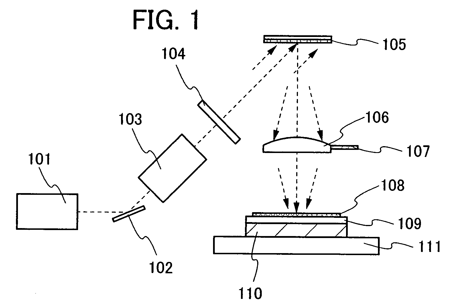
[0049]FIG. 1 shows a schematic block diagram of a laser irradiation apparatus of this embodiment mode. Note that in FIG. 1, the directions shown by dotted-line arrows are the traveling directions of a laser beam. Here, the laser beam emitted from a laser oscillator 101 is deflected by a mirror 102, and is incident on an expander 103. The expander 103 has a function to expand a beam diameter of the laser beam by placing, for example, two pieces of convex lenses.

[0050]Subsequently, the laser beam passed through the expander 103 is incident on a diffractive optical element 104. Here, the expander 103 is used to relax the limitation in designs such as a cut interval of the diffractive optical element 104 by expanding the beam diameter. Therefor...

embodiment mode 2

[0056]In this embodiment mode, an example in which a laser beam is divided into plural number by a reflection type diffractive optical element and is incident on a DMD to perform laser irradiation is described.

[0057]FIG. 3 shows a schematic diagram of a laser irradiation apparatus of this embodiment mode. In FIG. 3, a laser beam which is emitted from a laser oscillator 301 is incident on an expander 302. In addition, dotted-line arrows in FIG. 3 indicate the traveling directions of the laser beam. The expander 302 has a function to expand the beam diameter of the laser beam by placing, for example, two convex lenses. The laser beam which has passed through the expander 302 is incident on a reflection type diffractive optical element 303. Here, the expander 302 is used to relax limitation in designs such as a cut interval of the diffractive optical element 303. Therefore, when the beam diameter of the laser beam emitted from the laser oscillator is large enough, the expander 302 may ...

embodiment mode 3

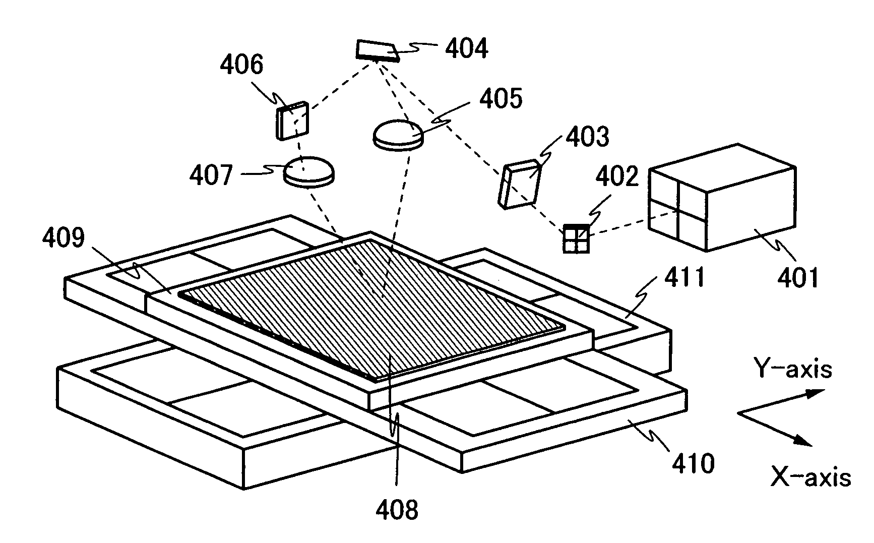
[0062]In this embodiment mode, described is an example in which laser beams that are reflected by a DMD in two directions are transferred to different regions on an irradiated surface to perform laser irradiation with improved throughput.

[0063]A perspective diagram of a laser irradiation apparatus of this embodiment mode is shown in FIG. 4. A laser beam emitted from a laser oscillator 401 is deflected by a mirror 402. The deflected laser beam passes through a diffractive optical element 403. The diffractive optical element 403 is used to divide the laser beam and form plural beam spots. Since the diffractive optical element 403 can be designed so that each of the plural laser beams that are divided has an equal beam parameter, even if, for example, a laser beam having a Gaussian energy distribution is used, the use of the diffractive optical element can realize formation of plural beam spots each having equal energy. Accordingly, each light-exposure time by the plural laser beams ca...


PUM

PropertyMeasurementUnit
tilt angleaaaaaaaaaa

Abstract

A laser irradiation apparatus and a method of laser irradiation which can improve use efficiency of a laser beam, eliminate an influence of stray light at a DMD, and form an irradiation pattern with a homogeneous beam spot are provided. The laser irradiation apparatus includes at least a laser oscillator, a diffractive optical element, and an optical element having many minute mirrors arranged two-dimensionally. A laser beam emitted from the laser oscillator is divided into plural laser beams by a diffractive optical element and the laser beams are deflected by plural micromirrors. The divided laser beams have equal energy to each other.

Description

BACKGROUND OF THE INVENTION[0001]1. Field of the Invention[0002]The present invention relates to a laser irradiation apparatus and a method of laser irradiation in order to efficiently perform laser irradiation in a laser direct imaging method or the like. In addition, the present invention relates to a method for manufacturing a semiconductor device with the use of a process of the laser irradiation.[0003]2. Description of the Related Art[0004]In manufacturing processes of a semiconductor device, a printed board, and the like, with an integration of a circuit, microfabrication is essential. In general, such microfabrication is performed by a laser light-exposure technology in which a photo mask with a circuit pattern written therein is made preliminarily and the pattern is transferred to a substrate. However, the method which uses the photo mask spends cost and time for making the mask. Therefore, in recent years, a process without the photo mask (herein after referred to as maskle...

Claims


Application Information

Patent Timeline
Patent Type & Authority Patents(United States)
IPC IPC(8): G02B26/08H01L21/00
CPCB23K26/067G03F7/70941G03F7/70291B23K26/083G02B26/0833G03F7/70025G03F7/70158
Inventor TANAKA, KOICHIROOISHI, HIROTADA
Owner SEMICON ENERGY LAB CO LTD
Why Eureka
Try Eureka