Reticulated and controlled porosity battery structures

a battery structure and porosity technology, applied in the field of bipolar devices, can solve the problems of reducing the energy density of the battery, reducing the discharge rate, and limiting the rate, and achieve the effect of facilitating the provision of energy

Inactive Publication Date: 2009-06-30
MASSACHUSETTS INST OF TECH
View PDF128 Cites 104 Cited by
  • Summary
  • Abstract
  • Description
  • Claims
  • Application Information

AI Technical Summary

Benefits of technology

[0028]In another embodiment, the present invention provides a method for facilitating providing energy. The method comprises the step of providing a battery comprising a first electrode, a second electrode, a first current collector in electronic communication with the first electrode and a second current collector in electronic communication with the second electrode, wherein the first electrode includes a portion, positioned between the first current collector and the second electrode, having a porosity that increases in a direction from the first current collector toward the second electrode.

Problems solved by technology

For example, an electrode in a lithium battery that is too thick can limit discharge rate because ion / electrode transport from the electrode to the interface with a separator, such as the electrolyte, can be rate limiting.
On the other hand, if the electrode layers are very thin, then energy density suffers because the electrolyte, separator, and current collectors occupy a higher volume and contribute to a greater mass relative to the active material of the electrodes.
In addition, the discharge rate can be limited by interface resistance allowing only a certain current rate per unit area of interface.

Method used


Image

  • Reticulated and controlled porosity battery structures
  • Reticulated and controlled porosity battery structures
  • Reticulated and controlled porosity battery structures

Examples


##ic example 1

Prophetic Example 1

Lithium Battery Prepared by Sequential Deposition

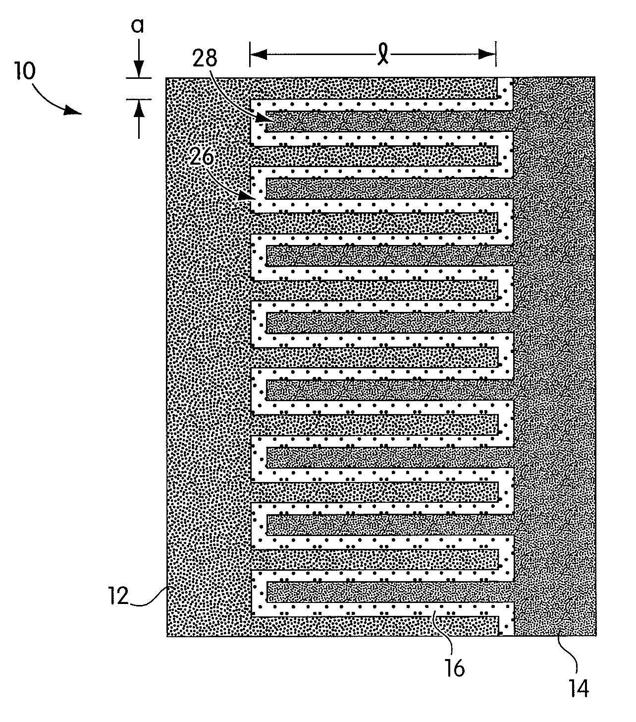
[0070]A suspension can be prepared of a fine powder lithium storage cathode such as LiCoO2, LiNiO2, LiMnO2, LiMn2O4, LiFePO4, V2O5, Li3Bi, Li3Sb, or other such cathodes well-known to those skilled in the art, in a solvent with a binder, optionally a conductive additive such as carbon, and other additives well-known to impart characteristics to the suspension allowing it to be deposited in thin layers using stenciling, screen printing, inkjet printing, or lithographic methods selected to allow a lateral resolution to the printed layer that is within the desired dimensional ranges. A separate like suspension can be prepared of a fine powder lithium storage anode such as carbon, Sn, Sb, Al, Zn, Ag, LiAl or other anode materials known to those skilled in the art. The cathode suspension and anode suspension are deposited layer by layer, providing a periodic or aperiodic reticulated or interdigitated structure as describe...

##ic example 2

Prophetic Example 2

Battery Produced by Printing and Coating

[0073]A first electrode with a reticulated or interdigitated structure, either cathode or anode, is prepared using the materials and methods of Example 1. At the free surface of the printed structure, a continuous film of a binder or polymer electrolyte can be formed. The film can form a physical separator between anode and cathode. The film can be formed by self-segregation (wetting) of the binder solution to the free surface of the printed electrode. Optionally, the surface film can be formed by coating with a liquid binder or electrolyte solution followed by drying, or by vapor deposition techniques known to those skilled in the art of thin film materials preparation.

[0074]A conformal coating of a liquid suspension can be applied to the formed structure to create the counter electrode. The indentations of the latter fill in complementary fashion to the structure of the first electrode, leaving a smooth and flat outer surf...

##ic example 3

Prophetic Example 3

Battery Produced by Embossing and Coating

[0075]A layer of a first electrode, either cathode or anode, formulated of the materials and by the methods of Example 1, is cast or coated in a layer upon a metal foil current collector or an insulating film. This layer is formulated by methods known to those skilled in the art to have rheological characteristics appropriate for thick film processing, for example, by screen printing, tape casting, web coating, and similar processes. The surface of the first layer is then embossed with a die to leave a reticulated surface with dimensions as desired. To this shaped surface is applied a counterelectrode by the conformal coating material and process described in Example 2. The assembly is dried and optionally heated for consolidation and a current collector is applied.

[0076]A film of binder or electrolyte is applied before or after the embossing step, and before coating with the counterelectrode formulation.

Prophetic Example N...


PUM

PropertyMeasurementUnit
lengthaaaaaaaaaa
average distanceaaaaaaaaaa

Abstract

The effective ionic conductivity in a composite structure is believed to decrease rapidly with volume fraction. A system, such as a bipolar device or energy storage device, has structures or components in which the diffusion length or path that electrodes or ions must traverse is minimized and the interfacial area exposed to the ions or electrons is maximized. The device includes components that can be reticulated or has a reticulated interface so that an interface area can be increased. The increased interfacial perimeter increases the available sites for reaction of ionic species. Many different reticulation patterns can be used. The aspect ratio of the reticulated features can be varied. Such bipolar devices can be fabricated by a variety of methods or procedures. A bipolar device having structures of reticulated interface can be tailored for the purposes of controlling and optimizing charge and discharge kinetics. A bipolar device having graded porosity structures can have improved transport properties because the diffusion controlling reaction kinetics can be modified. Graded porosity electrodes can be linearly or nonlinearly graded. A bipolar device having perforated structures also provides improved transport properties by removing tortuosity and reducing diffusion distance.

Description

[0001]This patent application claims priority to U.S. Provisional Patent Application No. 60 / 242,124 filed Oct. 20, 2000.BACKGROUND OF THE INVENTION[0002]1. Field of the Invention[0003]The present invention relates generally to bipolar devices, and more particularly, to batteries having electrodes that are reticulated, or interdigitated, a controlled porosity, and to those that are perforated.[0004]2. Description of the Related Art[0005]Solid state energy devices, such as but not limited to lithium batteries or fuel cells, typically require high energy density as well as high power density. Power density can be related to the discharge rate, which can be a function of ion and electron transport rates. For example, an electrode in a lithium battery that is too thick can limit discharge rate because ion / electrode transport from the electrode to the interface with a separator, such as the electrolyte, can be rate limiting. On the other hand, if the electrode layers are very thin, then e...

Claims


Application Information

Patent Timeline
Patent Type & Authority Patents(United States)
IPC IPC(8): H01M4/02C25C7/02H01G9/00H01M4/74H01M4/00H01M4/04H01M4/13H01M4/139H01M4/86H01M8/04H01M10/0525H01M10/36
CPCH01M4/04H01M4/0404H01M4/0414H01M4/0416H01M4/0421H01M4/0423H01M4/0426H01M4/0428H01M4/0471H01M4/0492H01M4/13H01M4/0402Y02E60/122H01M4/139H01M10/0525H01M2004/025Y02E60/10H01M4/74
Inventor CHIANG, YET-MINGHELLWEG, BENJAMIN
Owner MASSACHUSETTS INST OF TECH
Why Eureka
Try Eureka