Repair of gas turbine blade tip without recoating the repaired blade tip

a gas turbine and blade tip technology, applied in the direction of wind turbines with perpendicular air flow, machines/engines, climate sustainability, etc., can solve the problems of affecting the overall engine performance, the tip of some of the turbine blades may be damaged, and the damage to the blade is removed from service, so as to achieve significant reduction in the cost and processing time of the repair.

Active Publication Date: 2009-09-15
GENERAL ELECTRIC CO
View PDF16 Cites 31 Cited by
  • Summary
  • Abstract
  • Description
  • Claims
  • Application Information

AI Technical Summary

Benefits of technology

[0006]The present approach provides a method for repairing a gas turbine blade having a damaged blade tip region, and a repaired turbine blade. The present approach reduces the cost of the repair, by reducing the need for recoating of the repaired blade tip region.
[0013]The present approach avoids the need to perform the several steps of the recoating process for the non-ceramic coating. The cost and processing time of the repair are thereby significantly reduced, making the repair a more attractive option in the decision whether to repair the damaged turbine blade or to install an expensive new-make turbine blade. The performance of the turbine blade repaired according to the present approach is acceptable, both for mechanical properties and for environmental resistance.

Problems solved by technology

During service and despite the presence of the coating, the tips of some of the turbine blades may be damaged by rubbing contact with the stationary shroud of the gas turbine, by oxidation by the hot combustion gases, and by particle impacts.
If the damage becomes sufficiently severe to a turbine-blade tip so that the dimensions of the turbine blade are reduced to less than the specified minimum values and / or the overall engine performance becomes unacceptable, the damaged turbine blade is removed from service.
The damaged turbine blade may then be repaired and returned to service or discarded, but repair is preferred because of the high cost of each new turbine blade.

Method used


Image

  • Repair of gas turbine blade tip without recoating the repaired blade tip
  • Repair of gas turbine blade tip without recoating the repaired blade tip
  • Repair of gas turbine blade tip without recoating the repaired blade tip

Examples


Embodiment Construction

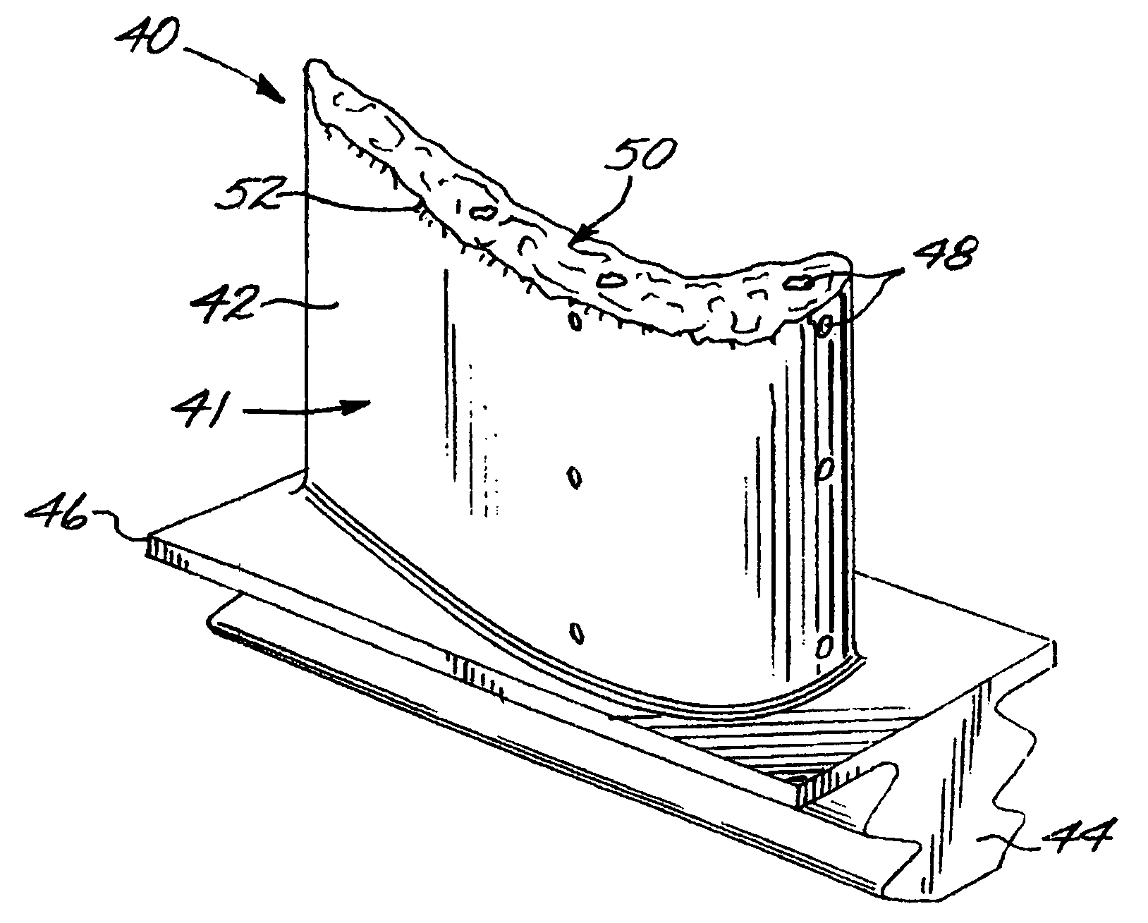
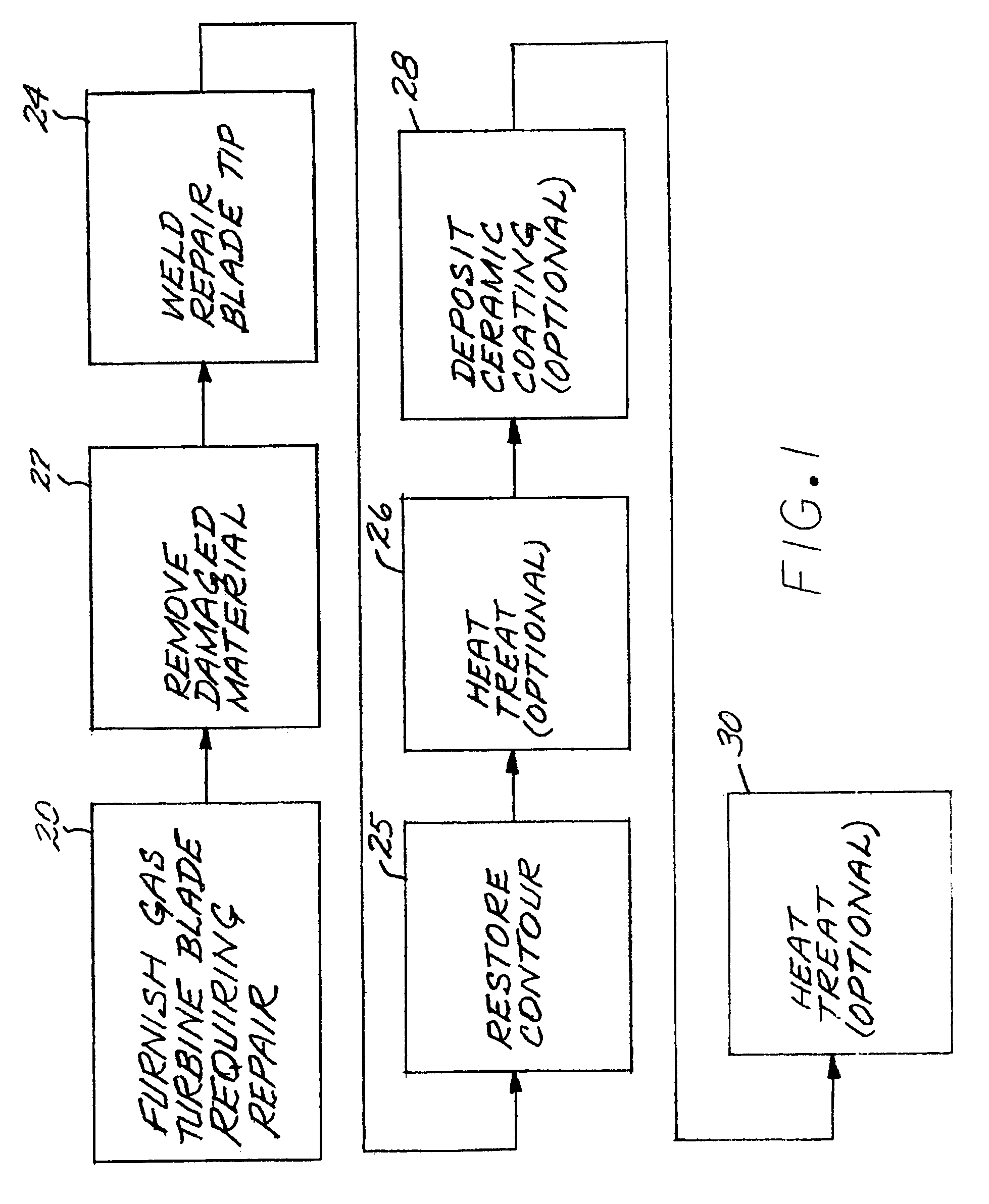
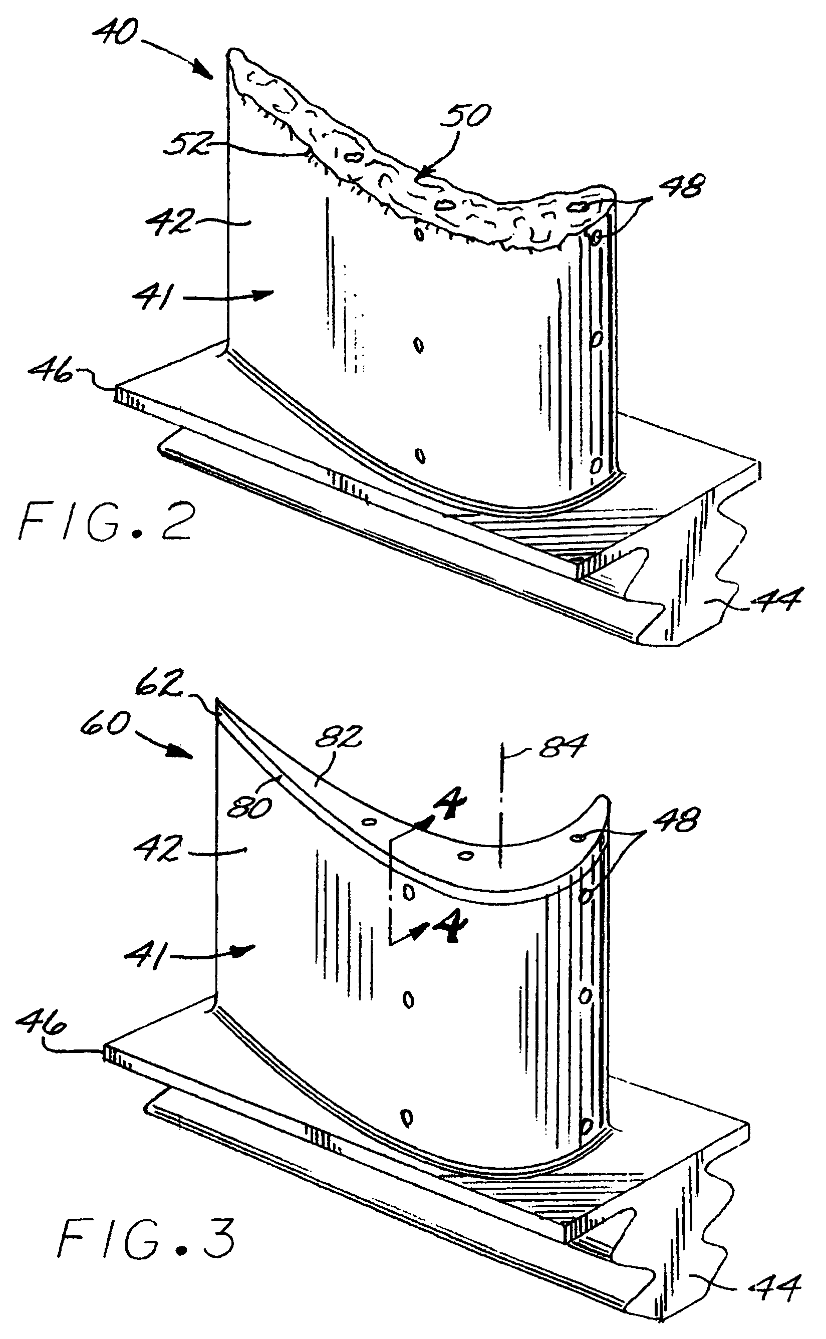
[0020]FIG. 1 depicts the steps in a method for repairing a damaged gas turbine blade 40 which has previously been in service, and which is illustrated in FIG. 2. The damaged gas turbine blade 40 requiring repair is furnished, step 20. The damaged gas turbine blade 40 has a body 41 that is made of a base metal. The base metal is preferably a nickel-base superalloy. A nickel-base alloy has more nickel than any other element. A nickel-base superalloy is strengthened by the precipitation of gamma prime and / or a related phase. An example of an operable nickel-base superalloy is Rene™ N5, having a nominal composition in weight percent of about 7.5 percent cobalt, about 7.0 percent chromium, about 1.5 percent molybdenum, about 5 percent tungsten, about 3 percent rhenium, about 6.5 percent tantalum, about 6.2 percent aluminum, about 0.15 percent hafnium, about 0.05 percent carbon, about 0.004 percent boron, about 0.01 percent yttrium, balance nickel. The body 41 of the gas turbine blade 40 ...


PUM

PropertyMeasurementUnit
temperatureaaaaaaaaaa

Abstract

A damaged gas turbine blade which has previously been in service, and which is made of a base metal, is furnished. Any damaged material is removed from the damaged blade tip. The damaged blade tip is weld repaired with a nickel-base superalloy that is more resistant to oxidation resistance than is the base metal in the operating environment of the tip-repaired gas turbine blade. The method does not include any step of coating a lateral surface of the repaired blade tip with a non-ceramic coating after the step of weld repairing.

Description

[0001]This invention relates to the repair of the damaged blade tip of a damaged gas turbine blade and, more particularly, to such a repair wherein the repaired blade tip is not recoated with a non-ceramic environmental coating or bond coat.BACKGROUND OF THE INVENTION[0002]In an aircraft gas turbine (jet) engine, air is drawn into the front of the engine, compressed by a shaft-mounted compressor, and mixed with fuel. The mixture is combusted, and the resulting hot combustion gases are passed through a turbine mounted on the same shaft. The turbine includes a rotor body with a series of turbine blades extending radially outwardly from the rotor body, and a stationary shroud that forms a tunnel in which the rotor body and its blades turn. The flow of combustion gas turns the turbine by contacting an airfoil portion of the turbine blade, which turns the shaft and provides power to the compressor. The hot exhaust gases flow from the back of the engine, driving it and the aircraft forwar...

Claims


Application Information

Patent Timeline
Patent Type & Authority Patents(United States)
IPC IPC(8): B23P6/00B63H1/26C21D1/00C21D1/09F04D29/44
CPCB23P6/007B32B15/01C22C19/057C23C26/02F01D5/005F01D5/20Y10T29/49734Y02T50/67Y02T50/673F05D2230/80Y10T29/49732Y10T29/49318Y02T50/60
Inventor GORMAN, MARK DANIELGROSSKLAUS, JR., WARREN DAVIS
Owner GENERAL ELECTRIC CO
Why Eureka
Try Eureka