Porous metal/organic polymeric composites

Inactive Publication Date: 2009-12-15
NAVY UNITED STATES OF AMERICA THE AS REPRESENTED BY THE SEC THE
View PDF21 Cites 34 Cited by
  • Summary
  • Abstract
  • Description
  • Claims
  • Application Information

AI Technical Summary

Benefits of technology

[0009]Accordingly, it is an object of this invention to produce a light st

Problems solved by technology

Both of these prior art approaches have had drawbacks.
Soft coupling components add weight to a device, may require maintenance, and may not be consistent with the required design and performance features.
Currently available acoustic damping materials do not exhibit adequate acoustic behavior ove

Method used


Image

  • Porous metal/organic polymeric composites
  • Porous metal/organic polymeric composites
  • Porous metal/organic polymeric composites

Examples


example 1

Preparation of Phthalonitrile Prepolymer

[0041]Phthalonitrile monomer, 4,4′-bis(3,4-dicyanophenoxy)biphenyl, was purchased from Daychem Laboratories. 10 g of the monomer was placed in an aluminum planchet and melted on a hot plate at 250° C. (monomer melts around 235° C.). The monomer melt was degassed for about 2 h to eliminate trace amounts of solvent present. The phthalonitrile prepolymer was synthesized by adding 0.15-0.168 g (1.5-1.68 wt %) of 1,3-bis(3-aminophenoxy)benzene, obtained from National Starch Corporation, to the monomer melt. The melt was stirred for 15 min. and was used for fabrication of phthalonitrile / metal foam composite specimens.

example 2

Fabrication of Phthalonitrile / Aluminum Foam Composite

[0042]An aluminum mold, 2×0.6″×0.2″, coated with a teflon mold release agent was used for fabrication of composite specimens. Two aluminum foam strips (1″×0.5″×0.185″, density 6-8% of the solid material, pore size—40 pores per inch (ppi)) separated by a teflon film, were placed in the mold and heated to 250° C. Approximately 2-3 g of the prepolymer melt synthesized as described above in Example 1 with 1.68 wt % curing additive was poured over the metal foam and degassed for about 15 min. with periodic venting to ensure a good flow of the resin throughout the metal foam. The mold was then heated in an air circulating oven for 9 h at 280° C. and cooled back to room temperature over a 3 h span. The composite samples made with this prepolymer showed an incomplete penetration of the resin into the metal foam. Therefore, subsequent composite fabrications involved a slower curing prepolymer made with 1.5% curing additive. The prepolymer ...

example 3

Fabrication of Phthalonitrile / Aluminum Foam Composite

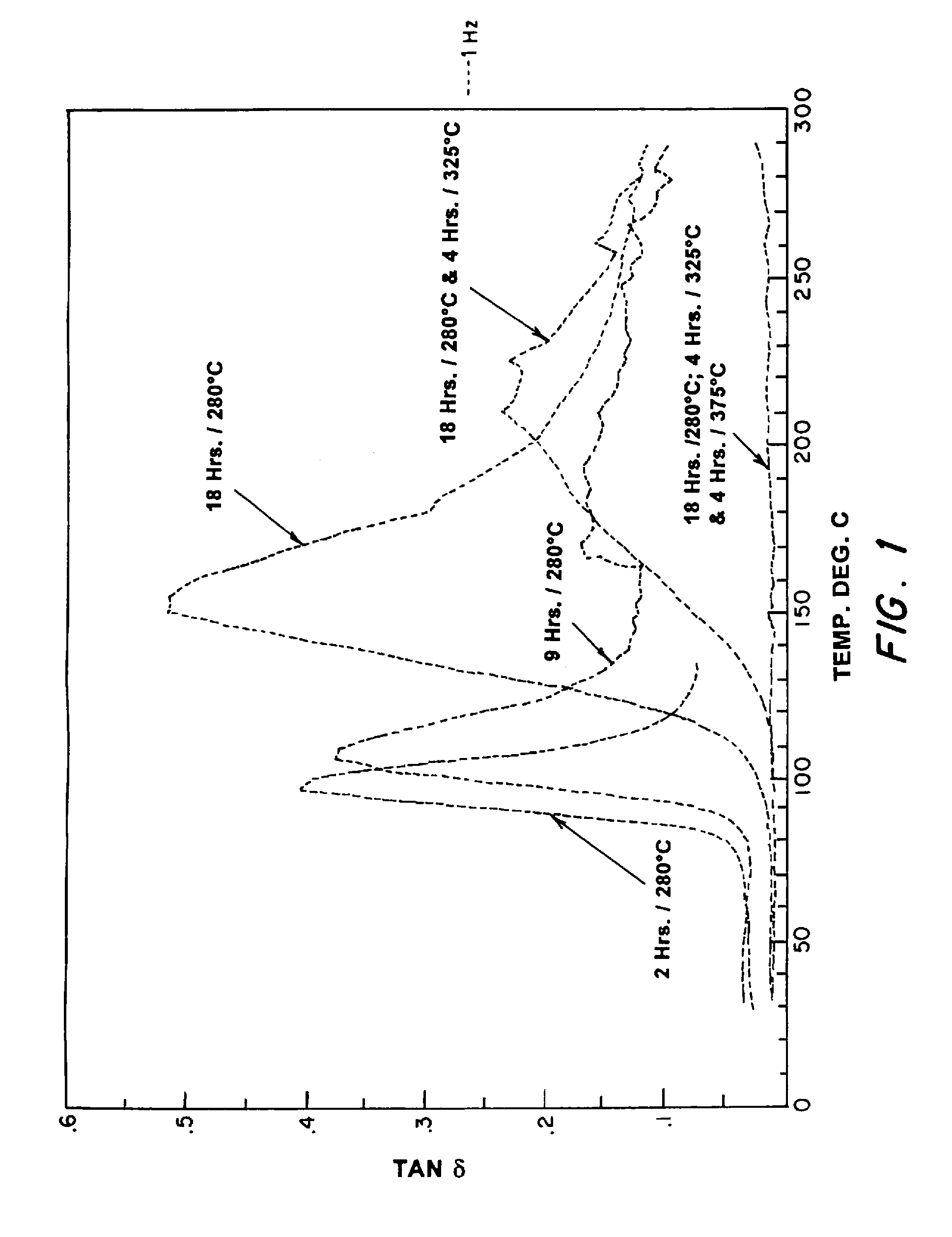
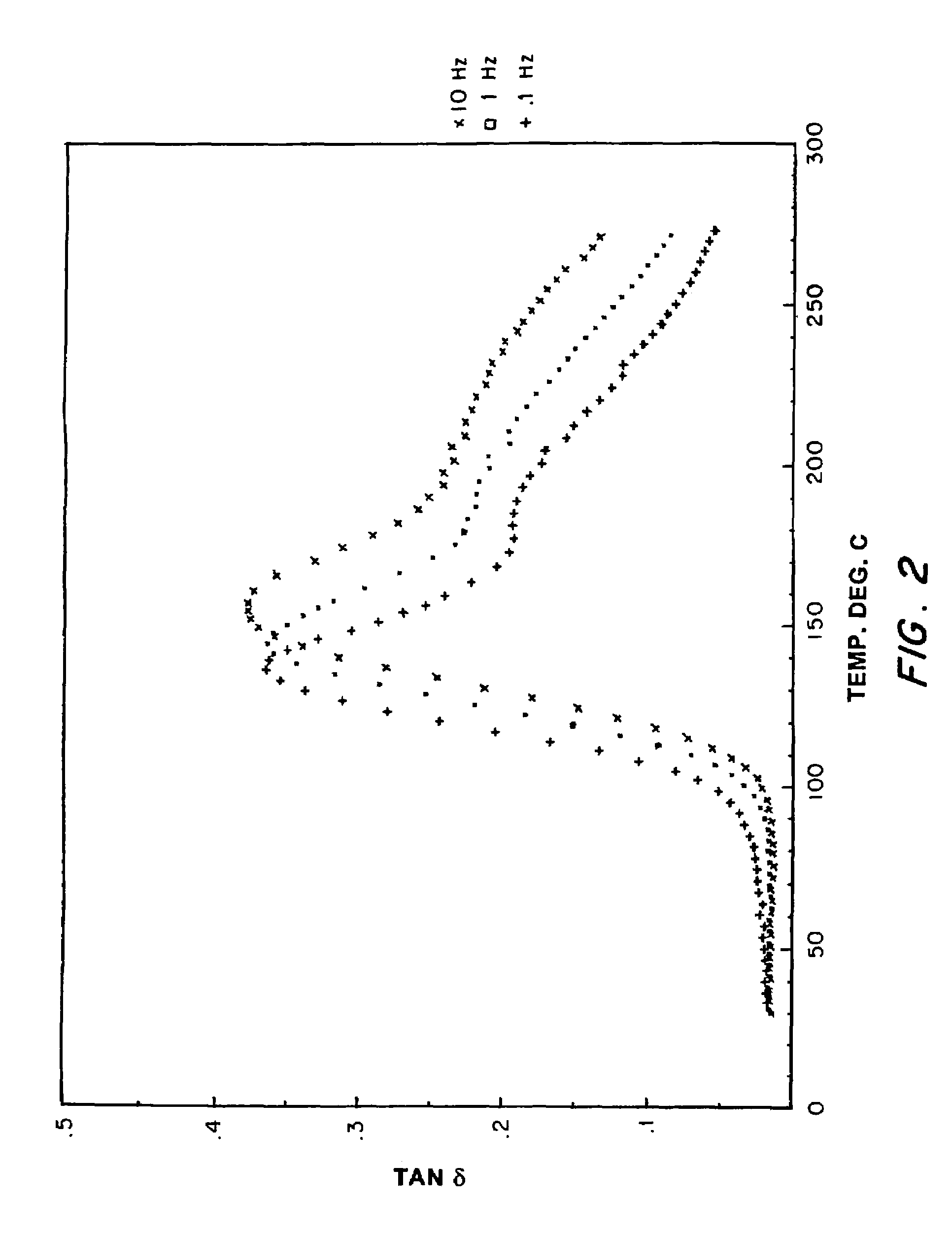
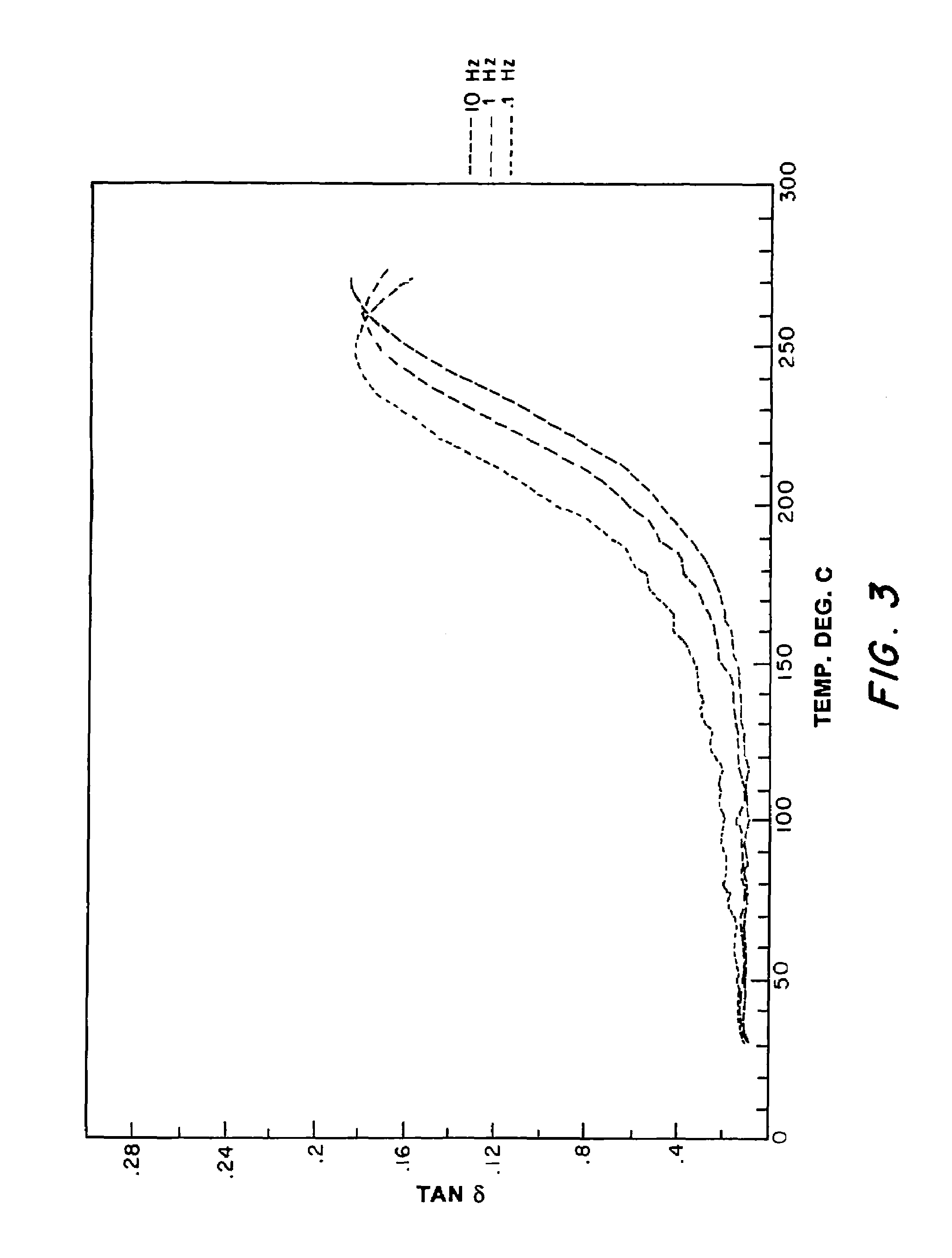
[0043]An aluminum mold, 2″×0.6″×0.2″, coated with a teflon mold release agent was used for fabrication of composite specimens. Two aluminum foam strips (1×0.5″×0.185″, density 6-8% of the solid material, pore size—40 ppi) separated by a teflon film, were placed in the mold and heated to 250° C. Approximately 2-3 g of the prepolymer melt synthesized with 1.5 wt % curing additive was poured over the metal foam and degassed for about 15 min. with periodic venting to ensure a good flow of the resin throughout the metal foam. The mold was then heated in an air circulating oven for 9 h at 280° C. and cooled back to room temperature over a 3 h span. The composite samples made with this prepolymer showed a complete penetration of the resin through the metal foam. The mechanical and damping properties of the phthalonitrile / aluminum composite samples were evaluated after heat treatment at the following conditions: (A) 9 h at 280° C. (B) 18 ...


PUM

PropertyMeasurementUnit
Thicknessaaaaaaaaaa
Diameteraaaaaaaaaa
Sizeaaaaaaaaaa

Abstract

Metal foams are impregnated with resins. The metal foam/polymer composite formed upon curing has excellent acoustic dampening and structural properties. Foams of various metals, such as aluminum, titanium, nickel, copper, iron, zinc, lead, silver, gold, platinum, tantalum, and alloys based on these metals, may be used. The polymer component may be any polymeric resin, for example, epoxy, natural rubber, acrylic, or phenolic.

Description

BACKGROUND OF THE INVENTION[0001]1. Field of the Invention[0002]The present invention relates generally to metal composites and more particularly to metal / polymer composites.[0003]2. Description of the Background Art[0004]In many cases, such as in factories, motor vehicles, ships, and submarines, it is desirable to absorb as much noise as possible. In factories, absorbance of machinery noises can minimize noise pollution caused by industrial sounds. In motor vehicles, absorbance of engine noises and noises from road vibration enhances driver and rider comfort. In submarines and ships, the absorbance of machinery sounds helps prevent detection and identification by unfriendly forces. Additionally, in regions where earthquakes are common, the structural components of buildings, bridges, and similar artifacts must not only be strong, but should be able to dampen vibrations.[0005]Past noise reduction efforts have previously taken one of two approaches. The use of soft coupling component...

Claims


Application Information

Patent Timeline
IPC IPC(8): B32B5/18B05D7/14B32B15/02E04B1/74E04B1/82G10K11/162
CPCB32B15/02E04B1/82G10K11/162E04B2001/742Y10T428/12556Y10T428/12479Y10T428/12493Y10T428/12021Y10T428/12042Y10T428/12736Y10T428/12007Y10T428/249961Y10T428/249991Y10T428/24997Y10T428/249992Y10T428/249956B32B2260/02B32B2260/046B32B2307/102B32B5/32B32B5/18B32B2311/24B32B2311/20B32B2266/06B32B2311/12
Inventor IMAM, M. ASHRAFRATH, BHAKTA B.KELLER, TEDDY M.
Owner NAVY UNITED STATES OF AMERICA THE AS REPRESENTED BY THE SEC THE
Why Eureka
Try Eureka