Auto-stopping slurries for chemical-mechanical polishing of topographic dielectric silicon dioxide

a topographic dielectric silicon dioxide and chemical-mechanical technology, applied in the direction of other chemical processes, manufacturing tools, chemistry apparatus and processes, etc., can solve the problems of disadvantageous thinning of the resultant ild layer, non-uniformity of polishing stop techniques, etc., to achieve moderate to elevated up area topography removal rate, reduce post-cmp non-uniformity, and prolong the effect of polishing tim

Active Publication Date: 2010-04-13
FERRO CORP
View PDF19 Cites 7 Cited by
  • Summary
  • Abstract
  • Description
  • Claims
  • Application Information

AI Technical Summary

Benefits of technology

[0009]In view of the foregoing, the present invention provides auto-stopping slurry compositions that minimize post-CMP non-uniformity and also extend the time that polishing can be continued beyond the end point without the risk of over-polishing the dielectric silicon dioxide film. Auto-stopping CMP slurry compositions exhibit a moderate to elevated up area topography removal rate (e.g., >5,000 Å / min), while simultaneously exhibiting a low down area removal rate. Furthermore, CMP slurry compositions according to the invention exhibit a relatively low removal rate (e.g., <1,000 Å / min) once substantial planarity has been achieved (i.e., once the up areas have been removed such that they are at or very near the level of the down areas). Auto-stopping CMP slurry compositions according to the invention can be used to effectively remove dielectric silicon oxide topography to leave a substantially planar surface. Furthermore, auto-stopping CMP slurry compositions according to the invention show very low pattern density dependency across a wide range of feature sizes and densities.

Problems solved by technology
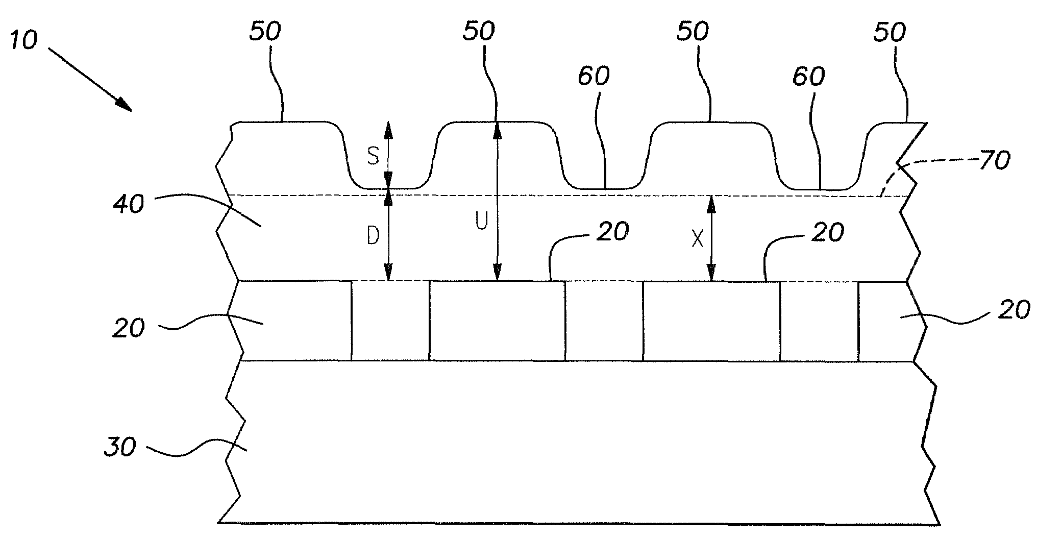
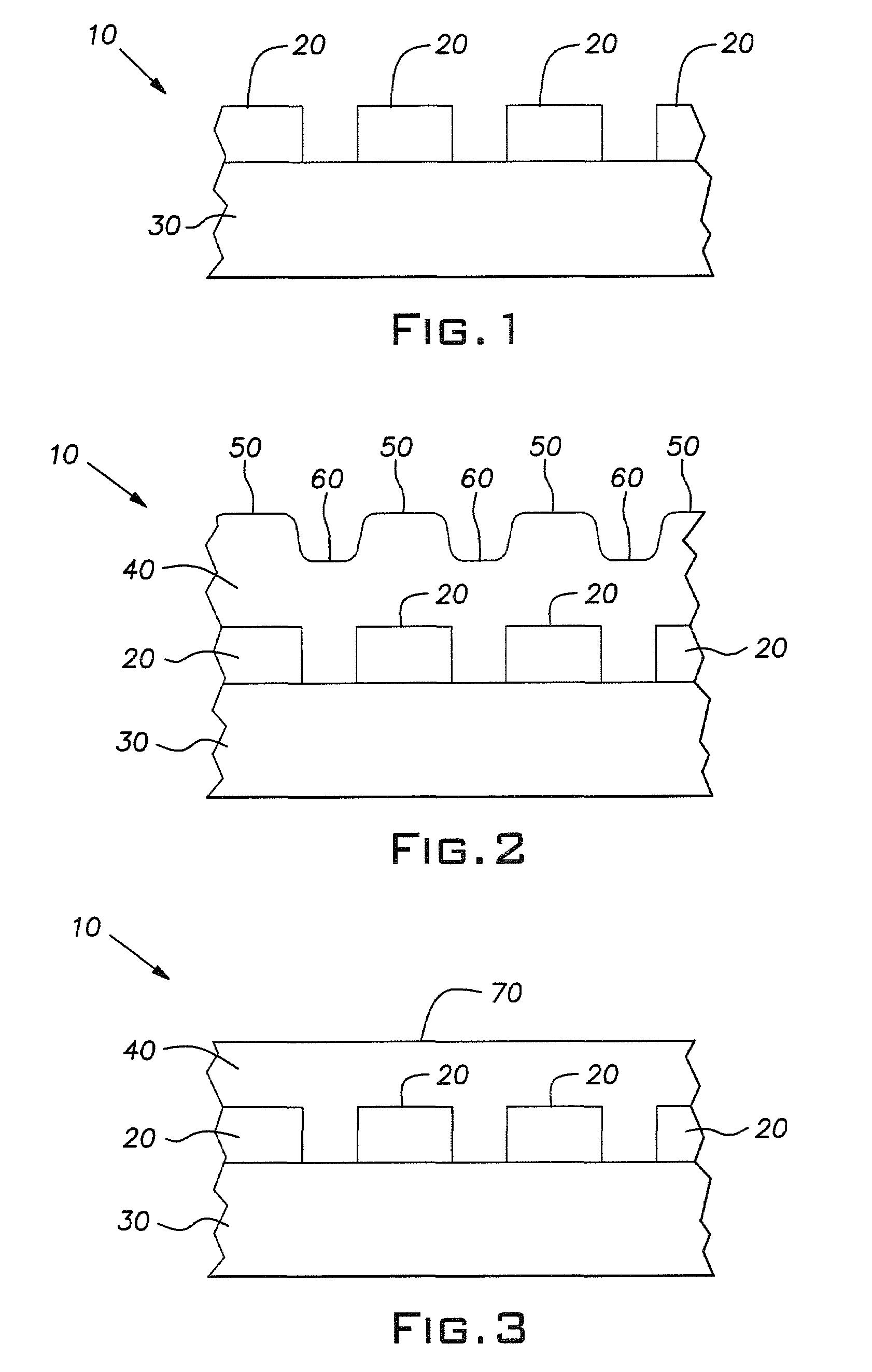
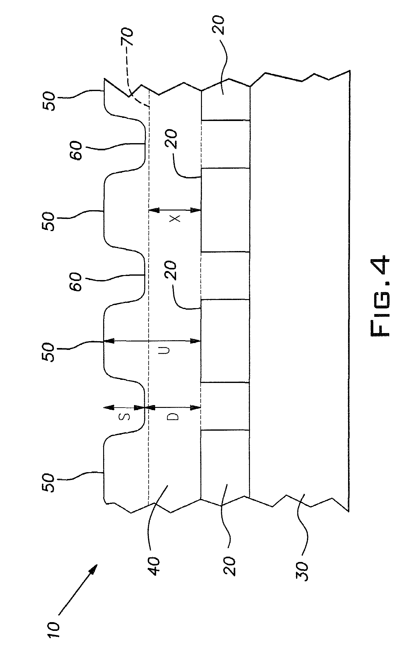
Both of these polishing stop techniques can produce non-uniformities across the polished silicon dioxide surface due to within-die topography variations and / or within-wafer polishing rate variations.
In addition, over-polishing, meaning polishing beyond the end point, tends to rapidly remove the dielectric silicon dioxide film layer thereby disadvantageously thinning the resultant ILD layer.

Method used


Image

  • Auto-stopping slurries for chemical-mechanical polishing of topographic dielectric silicon dioxide
  • Auto-stopping slurries for chemical-mechanical polishing of topographic dielectric silicon dioxide
  • Auto-stopping slurries for chemical-mechanical polishing of topographic dielectric silicon dioxide

Examples


example 1

[0040]Auto-stopping CMP Slurry 1 was formed by dispersing 2.0% ceria particles, 0.008% PEI and 0.1% of an ethylene oxide / propylene oxide nonionic block copolymer in water (all percentages stated by absolute weight of the resulting slurry). The ceria particles had an average primary particle diameter of 70 nm and an average secondary particle diameter of 180 nm. The PEI had a weight average molecular weight of about 10,000. The ethylene oxide / propylene oxide nonionic block copolymer had a weight average molecular weight of about 1,500. Nitric acid was added to adjust the pH of the slurry to 3.9.

[0041]Auto-stopping Slurry 1 was used to planarize pattern wafers containing features with various pitches and densities designed by MIT and Sematech. Before the CMP process, the average up oxide thickness of the pattern features was 37,500 Å and the average down oxide thickness of the pattern features was 20,000 Å. The thicknesses of up oxide and down oxide of nine 100-micron pitch / 70% densit...

example 2

[0044]Auto-stopping CMP Slurry 2 was formed by dispersing 6.0% ceria particles, 0.02% PEI and 0.3% of an ethylene oxide / propylene oxide nonionic block copolymer in water (all percentages stated by weight of the resulting slurry). The ceria particles had an average primary particle diameter of 70 nm and an average secondary particle diameter of 140 nm. The PEI had a weight average molecular weight of about 25,000. The ethylene oxide / propylene oxide nonionic block copolymer had a weight average molecular weight of about 1,500. Nitric acid was added to adjust the pH of the slurry to 4.7.

[0045]Auto-stopping Slurry 2 was used to planarize pattern wafers containing repeating features consisting of 3,200-micron wide / 3,200-micron long up oxide with adjacent 320-micron wide / 3,200-micron long down oxide throughout the entire wafer. Before CMP process, the average up oxide thickness of the pattern features was about 41,700 Å and the average down oxide thickness of the pattern features was abou...

example 3

[0051]COMPARATIVE CMP Slurry 3 was formed by dispersing 0.75% ceria particles and 0.075% ethylene oxide / propylene oxide nonionic block copolymer in water (all percentages stated by weight of the resulting slurry). The ceria particles had an average primary particle diameter of 70 nm and an average secondary particle diameter of 140 nm. The ethylene oxide / propylene oxide nonionic block copolymer had a weight average molecular weight of about 1,500. Nitric acid was added to adjust the pH of the slurry to 4.0. These slurry conditions were selected to produce a topography removal rate similar to that achieved using Auto-stopping CMP Slurry 2 from Example 2.

[0052]Auto-stopping CMP Slurry 2 and COMPARATIVE CMP Slurry 3 were used to polish 200 mm MIT / Sematech pattern wafers as described in Example 1, except that the wafers used for COMPARATIVE CMP Slurry 3 had thinner TEOS oxide thicknesses (the average up oxide thickness was 22,000 Å and the average down oxide thickness was 13,000 Å). The...


PUM

PropertyMeasurementUnit
mean volume secondary particle diameteraaaaaaaaaa
mean volume sizeaaaaaaaaaa

Abstract

The present invention provides auto-stopping CMP slurry compositions that minimize post-CMP non-uniformity and also extend the time that polishing can be continued beyond the end point without the risk of over-polishing the dielectric silicon dioxide film. Auto-stopping CMP slurry compositions according to the invention include ceria abrasive particles and an effective amount of a polyalkylamine such as polyethyleneimine dispersed in water. The methods of the invention include polishing a topographic dielectric silicon dioxide film layer using the auto-stopping CMP slurry compositions to obtain a dielectric silicon dioxide surface having a desired predetermined minimum step height.

Description

BACKGROUND OF INVENTION[0001]1. Field of Invention[0002]The present invention relates to auto-stopping slurry compositions for polishing topographic dielectric silicon dioxide film layers and a method of planarizing topographic dielectric silicon dioxide film layers using the same.[0003]2. Description of Related Art[0004]One of the primary applications for chemical-mechanical polishing (“CMP”) in integrated circuit (“IC”) fabrication is the planarization of topographic dielectric silicon dioxide film layers (e.g., to form inter-level dielectric (“ILD”) layers and as a first step in shallow trench isolation (“STI”) processing). For purposes of illustration, the ILD CMP process is schematically depicted in FIGS. 1-3.[0005]FIG. 1 shows a side sectional view of a portion of an IC device 10 prior to ILD layer formation. The IC device 10 includes a plurality of features 20 formed on a dielectric substrate 30, which is typically elemental silicon or a previously formed ILD layer. In the il...

Claims


Application Information

Patent Timeline
Patent Type & Authority Patents(United States)
IPC IPC(8): H01L21/302
CPCC09G1/02H01L21/31053C09K3/1463
Inventor OSWALD, ERICFRINK, SEANKRAFT, BRADLEYSANTORA, BRIAN
Owner FERRO CORP
Why Eureka
Try Eureka