Carbon nano-fibrous rod, fibrous nanocarbon, and method and apparatus for producing fibrous nanocarbon

a carbon nanofiber and fibrous technology, applied in the direction of carbonsing rags, liquid-gas reaction processes, chemistry apparatus and processes, etc., can solve the problems of inability to achieve mass production, inability to serve as materials, and inability to diversify conventional carbon nanofibers

Active Publication Date: 2010-04-20
MITSUBISHI HEAVY IND LTD +2
View PDF24 Cites 26 Cited by
  • Summary
  • Abstract
  • Description
  • Claims
  • Application Information

AI Technical Summary

Benefits of technology

[0029]A nineteenth embodiment for attaining the aforementioned object is a method for producing a fibrous nanocarbon comprising an aggregate of carbon nano-fibrous rods by reacting a carbon material in a high temperature fluidized bed with the use of a catalyst, characterized by using, as a fluid material, a dual-purpose catalyst / fluid material comprising a metal catalyst-supporting carrier bound via a binder. The method comprises performing a first gas supply step of supplying a reducing gas, a carbon material supply step of supplying the carbon material in a gaseous state to produce a carbon nano-fibrous rod in the presence of the metal catalyst of the dual-purpose catalyst / fluid material, and a second gas supply step of supplying a carbon-free gas to eliminate the fluidizing function of the dual-purpose catalyst / fluid material.
[0039]A twenty-ninth embodiment is a method for producing fibrous nanocarbon according to the twenty-eighth embodiment, characterized by controlling the particle diameter of the metal catalyst of the dual-purpose catalyst / fluid material and finely dividing the metal catalyst, thereby controlling the diameter of the fibrous nanocarbon obtained.

Problems solved by technology

However, the conventional carbon nanofibers have no diversity because of their prescribed simple structures, and have not served as materials which fulfill diverse functions at the same time.
The conventional apparatus, as shown in FIG. 50, therefore, has posed the problem that mass production cannot be performed.
However, with the basic reactor shown in FIG. 50 or the vapor phase flow process as shown in FIG. 51, the problem occurs that the interior of the reaction tube 03 tends to cause a temperature distribution and a non-uniform temperature.
There is also the problem that the grown product is prone to deposit on the inner wall surface of the reaction tube 03, making it difficult to recover the product.
This presents the problem that the production on an increased scale is difficult.

Method used


Image

  • Carbon nano-fibrous rod, fibrous nanocarbon, and method and apparatus for producing fibrous nanocarbon
  • Carbon nano-fibrous rod, fibrous nanocarbon, and method and apparatus for producing fibrous nanocarbon
  • Carbon nano-fibrous rod, fibrous nanocarbon, and method and apparatus for producing fibrous nanocarbon

Examples


example 4

[0265]The present example is an example in which the fibrous nanocarbon of Example 3 was heat-treated at a high temperature.

[0266]That is, the fibrous nonocarbon prepared in Example 3 was heated-treated for 10 minutes at 2,000° C. and 2,800° C. in an argon atmosphere.

example 5

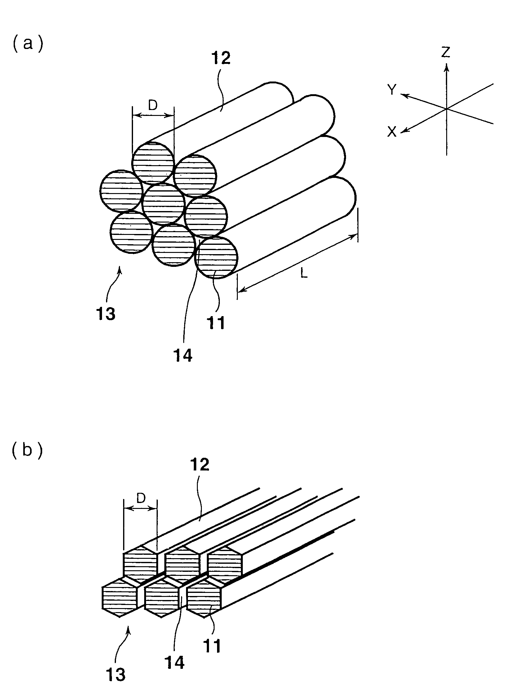
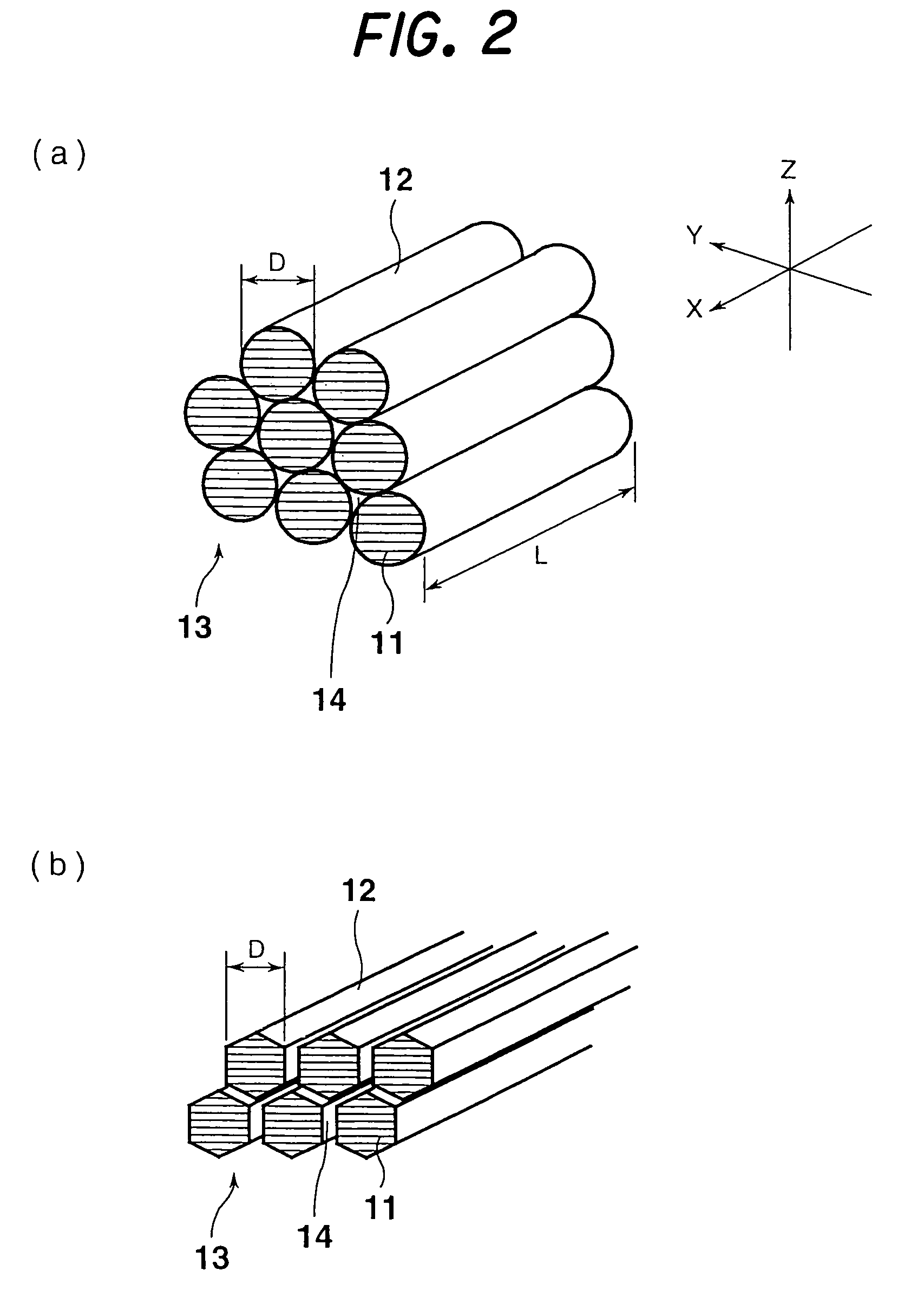
[0267]The present example is fibrous nanocarbon of a tubular structure.

[0268]A iron-nickel alloy catalyst was prepared by the precipitation method of Example 1 with the use of iron nitrate and nickel nitrate.

[0269]In particular, 11.90 g of nickel nitrate (NiNO3.xH2O: a first class grade chemical, Wako Pure Chemical Industries) and 11.80 g of iron nitrate (FeNO3.9H2O: a first class grade chemical, Wako Pure Chemical Industries) were added to 200 ml of pure water in order to prepare 4 g of an iron-nickel catalyst, and the mixture was slowly stirred to prepare a solution. To the solution, ammonium hydrogen carbonate (NH4HCO3, a first class grade chemical, Junsei Yakuhin Kogyo) was added with stirring until a precipitate (NiCO3.xH2O) was formed. Then, the precipitate was filtered off, and purified with pure water until ammonium hydrogen carbonate vanished. Then, the precipitate was filtered off, and purified with pure water until ammonium hydrogen carbonate vanished. The purified precip...

example 6

[0272]The present example is an example in which the fibrous nanocarbon of Example 5 was heat-treated at a high temperature.

[0273]In particular, the fibrous nonocarbon prepared in Example 5 was heated-treated for 10 minutes at 2,000° C. and 2,800° C. in an argon atmosphere.

Measurement of X-Ray Diffraction

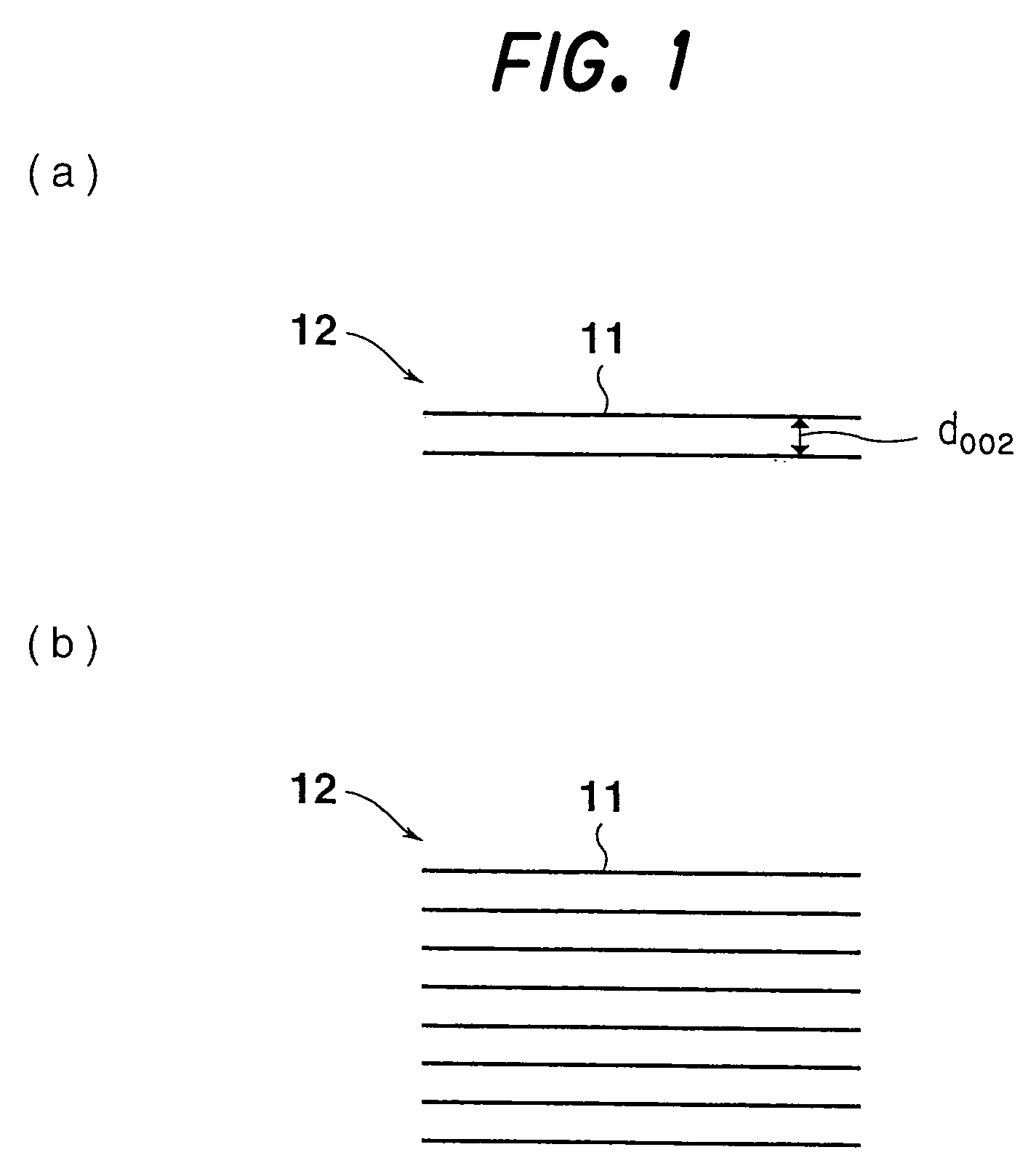
[0274]The fibrous nanocarbons (150 mg) obtained in Examples 1 to 6 were each mixed with 15 mg of standard silicon, and diffraction at angles of 5° to 90° was performed (CuKα rays, 40 kV, 30 mA, stepwise method) using a wide angle X-ray diffractometer (a product of Rigaku), whereby diffraction patterns were obtained.

[0275]From the resulting X-ray patterns, the interplanar distance (d002), the size of the stack (Lc002), and the size of the crystallite (La110) were calculated by the Gakushin method. The results are shown in the aforementioned Table 1.

Observation by Electric Field Scanning Transmission Electron Microscope

[0276]To investigate the fiber diameter and structure of the fibro...


PUM

PropertyMeasurementUnit
lengthaaaaaaaaaa
arrangement angleaaaaaaaaaa

Abstract

A carbon nano-fibrous rod including a predetermined number of hexagonal carbon layers extending in one direction, and a fibrous nanoncarbon which includes a plurality of the carbon nano-fibrous rods three-dimensionally gathered are disclosed.

Description

BACKGROUND OF THE INVENTION[0001]1. Field of the Invention[0002]This invention relates to a carbon nano-fibrous rod (carbon nanorod), fibrous nanocarbon, and a method and apparatus for producing fibrous nanocarbon.[0003]2. Description of the Related Art[0004]In recent years, a carbon nanofiber (in 1983, United States of America, Hyperion Catalytic International, Japanese Patent Application Laid-Open No. 1987-5000943, Multi-walled Nanotube, The number of walls varies, with 8 to 15 being typical. The outside diameter of the tube is approximately 10 to 15 nanometers. The inside diameter is approximately 5 nanometers. Nanotubes are typically tens of microns in length. Aspect ratios on the order of 100 to 1000), (H. P. Boehm, Carbon, 11, 583 (1973), H. Murayama, T. Maeda, Nature, 245, 791, Rodriguez, N. M. 1993. J. Mater. Res. 8:3233), and carbon nanotube (S. Iijima, Nature, 354, 56 (1991), S. Iijima), for example, have been discovered as carbon materials on the order of nanometers (nm=o...

Claims


Application Information

Patent Timeline
Patent Type & Authority Patents(United States)
IPC IPC(8): D01F9/12D01C5/00C01B31/02D01F9/127D01F9/133
CPCB82Y30/00B82Y40/00C01B31/02D01F9/133C01B31/0293D01F9/127D01F9/1273C01B31/0233C01B32/05C01B32/162C01B32/18
Inventor FUJIOKA, YUICHIYASUTAKE, AKINORISETOGUCHI, TOSHIHIKOMOCHIDA, ISAOYOON, SEONG-HO
Owner MITSUBISHI HEAVY IND LTD
Why Eureka
Try Eureka