Dynamic control of selective non-catalytic reduction system for semi-batch-fed stoker-based municipal solid waste combustion

a non-catalytic reduction and control system technology, applied in the direction of machines/engines, separation processes, mechanical equipment, etc., can solve the problems of nox emissions that are generally undesirable, worsen potentially fatal respiratory diseases, and are susceptible to adverse effects, so as to improve the ammonia flow, accurate predict current furnace nox levels, and eliminate the delay inherent in the nox measurement device

Active Publication Date: 2010-05-11
COVANTA ENERGY CORPORATION
View PDF10 Cites 15 Cited by
  • Summary
  • Abstract
  • Description
  • Claims
  • Application Information

AI Technical Summary

Benefits of technology

[0021]In response to these and other needs, embodiments of the present invention provide a system and method for controlling reagent flow levels in a SNCR system in MWCs by basing reagent levels on measured aspects that more accurately predict current furnace NOx levels over the short term. In one embodiment, the reagent levels correspond with measured furnace temperatures. The new approach uses a rapidly responding ammonia flow to increase ammonia during high NOx periods and to reduce it during low NOx periods, but relies on a real-time temperature measurement in the furnace as a surrogate for NOx. This eliminates the delay inherent in the NOx measurement device. As a result, ammonia flow is increased during the high temperature portion of the combustion cycle when NOx generation is higher and then reduced during the low temperature portions corresponding to lower NOx generation, thus improving NOx reduction and reducing ammonia slip by minimizing the excess application of the reagent.
[0023]Linking a combustion control system to the SNCR system to provide a feed-forward signal to the SNCR control can further enhance the SNCR control process. This linkage would allow reagent flow to be increased in anticipation of higher NOx levels and decreased in anticipation of lower NOx levels. In this embodiment, the fast controller may use other collected data to more accurately predict changes in the NOx levels and to make appropriate corrections to the reagent levels. For example, another embodiment of the present invention includes a fast controller that include two additional signals that are added individually or together to maximize Nox control while minimizing slip. The two signals are a feed forward signal from a combustion controller and a feedback signal from an ammonia analyzer downstream of the combustion zone.

Problems solved by technology

However, NOx emissions are generally undesirable and are of environmental significance because of their role as a criteria pollutant, acid gas, and ozone precursor.
These and other particles produced from NOx penetrate deeply into sensitive parts of the lungs and can cause or worsen potentially fatal respiratory diseases such as emphysema and bronchitis.
In addition, the emissions of NOx pose other environmental concerns.
Children, asthmatics, and people who work or exercise outside are susceptible to adverse effects from the ozone, and these effects include lung tissue damage and decreased lung function.
Ozone also damages vegetation and reduces crop yields.
Acid rain damages or deteriorates cars, buildings and monuments, as well as causes lakes and streams to become unsuitable for fish.
Combustion controls limit the formation of NOx during the combustion process by reducing the availability of O2 within the flame and lowering combustion zone temperatures.
As described in greater detail below, SCR systems are many times more expensive to build, operate, and maintain than SNCR systems and are consequently not economically feasible for use on waste-to-energy (WTE) plants in many parts of the world.
SCR systems typically operate at temperature of approximately 500-700° F. In terms of waste disposal fee impact and cost effectiveness, SCR generally has higher costs resulting from high capital costs, as well as the cost of catalyst replacement and disposal.
When operating the SNCR systems near the upper end of their performance range, however, excess reagent may be added to the reactor chamber, and the excess reagent passes through the MWC and ultimately escapes into the atmosphere, an undesirable phenomena known as ammonia slip.
If tighter NOx limits or shorter averaging periods are required, however, this known approach using measured NOx emissions levels to control reagent levels results in potentially diminished NOx reduction and higher ammonia slip.
In particular, simply speeding up the response of the ammonia flow to the stack NOx signal is ineffective because of the time delay between NOx generation in the furnace and NOx measurement in the Continuous Emissions Monitoring (CEM) system that monitors stack emissions from the MWC.
When the additional reagent is applied during subsequent periods of lower NOx levels, the increased ammonia flow may be excessive, causing increased ammonia slip.
Likewise, the SNCR system responds to a temporary decrease in NOx stack emissions by decreasing reagent flow, and the decreased levels of reagent flow may be inadequate to optimally address relatively higher NOx furnace levels.
When controlling to stricter limits in processes with highly variable NOx emissions, past NOx levels are no longer a good indication of current NOx levels.
However, ammonia slip levels, in themselves, may have little relevance to NOx levels, so adjusting the reagent level to minimize ammonia slip may provide relatively poor NOx reduction performance.
In addition, the ammonia slip criteria of controlling SNCR system suffers from a similar deficiency to the NOx-based control systems in that the measured levels of current ammonia slip in the emissions, in itself, provides limited guidance about the reagent flow needed to address current future furnace conditions and resulting NOx levels in the furnace.

Method used


Image

  • Dynamic control of selective non-catalytic reduction system for semi-batch-fed stoker-based municipal solid waste combustion
  • Dynamic control of selective non-catalytic reduction system for semi-batch-fed stoker-based municipal solid waste combustion
  • Dynamic control of selective non-catalytic reduction system for semi-batch-fed stoker-based municipal solid waste combustion

Examples


Embodiment Construction

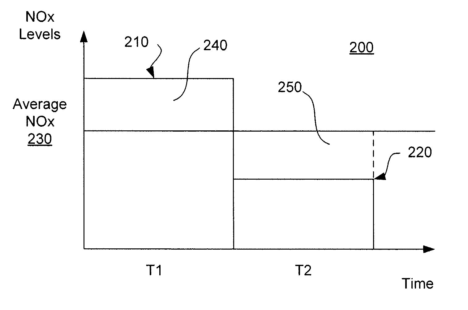
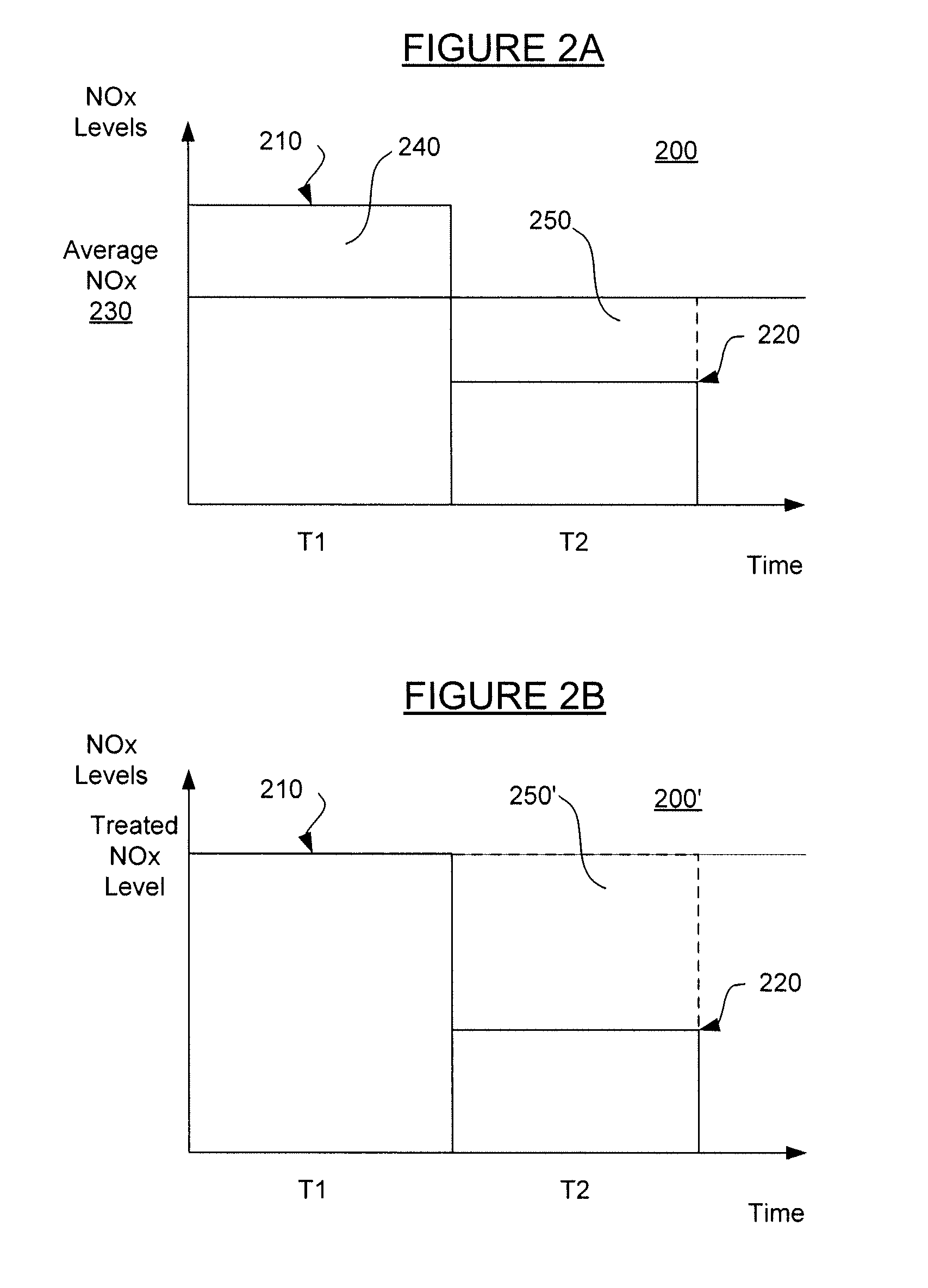
[0034]As depicted in the figures and as described herein, the present invention provides an improved method and system for controlling selective non-catalytic reduction (SNCR) systems in municipal waste combustors (MWCs) to reduce both Nitrogen Oxides (NOx) emissions and ammonia slip.

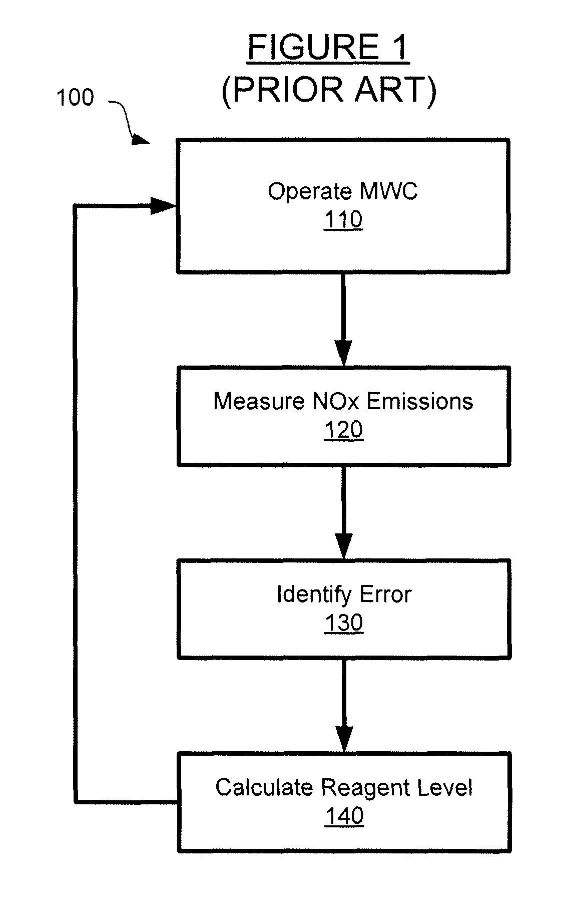
[0035]Turning now to FIG. 1, a known method 100 for controlling SNCR systems is described. In the known SNCR control method 100, a MWC facility is operated in step 110. The stack NOx emissions from the MWC over one or more periods is then measured in step 120. In step 130, a proportional-integral-derivative (PID) controller is used to identify the error between the measured NOx emissions level and a desired setpoint. As known in the art, the PID controller calculation involves three separate parameters: the Proportional, the Integral and Derivative values. The weighted sum of these three parameters is used to adjust the process via a control element. Then, in step 140, a corrective reagent level (i.e., ...


PUM

PropertyMeasurementUnit
temperaturesaaaaaaaaaa
flame temperaturesaaaaaaaaaa
temperatureaaaaaaaaaa

Abstract

The present invention controls reagent flow levels in a selective non-catalytic reduction (SNCR) system by more accurately predicting Nitrogen Oxides (NOx) production with a municipal waste combustor. In one embodiment, the reagent levels correspond with measured furnace temperatures. The reagent levels may have a baseline level from prior measured NOx that is then modified according to temperatures measurements. A slow controller may use NOx measurements over an extended period to define a base regent level, and a fast controller may use additional information such as the furnace temperature to modify the base regent level. The fast controller may further receive two additional signals that are added individually or together to maximize NOx control while minimizing ammonia slip from the reagent. The two signals are a feed-forward signal from the combustion controller and a feedback signal from an ammonia analyzer downstream of the combustion zone.

Description

CROSS REFERENCE TO RELATED APPLICATIONS[0001]This application claims priority under 35 U.S.C. §119(e) from U.S. Provisional Patent Application No. 60 / 876,559 filed on Dec. 22, 2006, the subject matter of which is herein incorporated by reference.FIELD OF THE INVENTION[0002]The present invention relates to an improved control system for a selective non-catalytic reduction (SNCR) system that uses a reagent such as ammonia or urea to reduce nitrogen oxides (NOx) emissions from a waste-to-energy boiler. Specifically, the improved control system allows the SNCR system to achieve desirable NOx reductions while also better minimizing the undesired excess application of the reagent, thus reducing ammonia emissions from the stack.BACKGROUND OF THE INVENTION[0003]The combustion of solid waste in a Municipal Waste Combustor (MWC) generates some amount of nitrogen oxides (NOx). NOx is the generic name for a group of colorless and odorless but highly reactive gases that contain varying amounts o...

Claims


Application Information

Patent Timeline
Patent Type & Authority Patents(United States)
IPC IPC(8): F01N3/00
CPCB01D53/56B01D2251/2062
Inventor WHITE, MARK L.DEDUCK, STEPHEN G.
Owner COVANTA ENERGY CORPORATION
Why Eureka
Try Eureka