Joining the mixing and variable gas atomizing of reactive chemicals in flue gas cleaning systems for removal of sulfur oxides, nitrogen oxides and mercury

a technology of reactive chemicals and flue gas cleaning, which is applied in the direction of lighting and heating apparatus, combustion types, and separation processes, can solve the problems of limiting the removal success of sulfur dioxide on a full scale level, affecting the efficiency of removal, and affecting the quality of removal, so as to achieve rapid wetting, reduce the effect of recirculation eddies and low cos

Inactive Publication Date: 2010-06-08
WALSH JR WILLIAM ARTHUR
View PDF22 Cites 9 Cited by
  • Summary
  • Abstract
  • Description
  • Claims
  • Application Information

AI Technical Summary

Benefits of technology

[0030]In accordance with the present invention, methods and apparatus are provided which employ and expand upon the atomization means and teachings VGA. This invention includes modifications to VGA nozzles and nozzle-enclosing lances for flue gas cleaning by duct injection. In combination with associated flue gas duct modifications, they are intended to provide an affordable retrofit or new installation cost for power plant flue gas cleaning systems.
[0031]One VGA nozzle modification enables water or aqueous solutions or slurries plus dry hydrated lime or other dry chemicals or combinations thereof to be separately fed within the same nozzle-lance and to react together during and / or immediately following the atomization of the liquids. It divides the flow of the secondary air so that a portion of it intersects the entraining gas and solids mixtures and sweeps them away from the nozzle face. The other portion flows over the nozzle face to furnish the immediate entrainment flow demand by the expanding compressed. In so doing it minimizes recirculation eddies and deposition of solids on the nozzle face. The carrier-air-conveyed dry chemical, which is delivered within the same nozzle enclosure, is entrained by aspiration into the spray plume exiting the nozzle. The immediate mixing of the dry chemicals and water droplets enables the surface of the particles to be rapidly wetted and more effectively readied for reaction with targeted gaseous components of the combustion gas stream. By joining the water atomization and dry sorbent injection, surface wetting is increased in comparison with downstream injection in which the flue gas is already partially cooled by the very rapid evaporation of a large portion of the finer droplets in the spray. With upstream injection of dry sorbent, the sorbent can become pre-heated prior to exposure to spray droplets and increased water vapor, thereby decreasing the water vapor condensation on the particle surface.
[0032]Another VGA nozzle modification simultaneously mixes and atomizes reactive chemicals so that their volatile reaction products can be effectively utilized for further reaction with specific constituents of the flue gas stream. Reactive chemicals are separately fed to the region of mixing and atomization, within the exit throat zone of a gas atomizing nozzle. One example is the formation of chlorine dioxide (ClO2), a highly reactive, free radical, oxidizing agent (e.g., by mixing sodium chlorate, an acid and a catalyst as generally employed in its commercial production). Its formation during atomization and release into the flue gas stream avoids the explosively hazardous gas generation that can result from pre-mixing. Another example is the formation of nascent oxygen and hydroxyl groups from decomposition of hydrogen peroxide by mixing acids and catalysts with it during atomization. Such intermediates are immediately employed (before their degradation or recombination) for their reaction with specific constituents of the flue gas stream. The immediate release of the finely atomized droplets of reacting chemicals into the adjoining, hot, flue gas stream (being aspirated by the expanding, high velocity atomizing air) enables the volatile reaction products to effectively react further with targeted flue gas constituents.

Problems solved by technology

The need for providing cost-effective removal of the deleterious constituents emitted in the combustion of coal and other fossil fuels has long plagued the utility industry.
To date, successful removal on a full scale level has been limited to sulfur dioxide, the primary acid rain producing constituent emitted in coal combustion.
Because both of these methods involve high capital and operating costs, their installation has been generally limited to larger and newer power plant units.
In these cases, the high costs are ameliorated by scale-up factors.
Neither of these methods removes the nitrogen oxides or mercury present.
Although it showed promise as a lower cost method, it was nevertheless abandoned.
This was primarily because many of the existing plants had been grandfathered in the 1970's under the Clean Air Act enactments, but also because of its limited technical success.
Many of the existing US, coal-fired utilities subsequently converted to low-sulfur coal in the 1990's in an effort to meet the sulfur dioxide emission limitations; however, these non-scrubbed units will not meet the recent new reduced emission limits.
Coupled with the slowdown in retrofitting during the implementation of the Clean Air Act Amendments, major generic retrofit-design problems remained.
These prevented adequate conceptual design and field development for duct injection and its adoption by industry.
In addition an excessively large amount of hydrated lime (calcium / sulfur ratio of 2.5 to 3 times the theoretical) was required, which resulted in excessively high cost of reagent and waste disposal.
It is believed by this writer that the operating conditions that prevailed in the test programs prevented near completion of the chemical reaction and, thereby, reduced the overall performance.
Contributing factors to these limitations were the comparatively large droplet sizes produced by the commonplace nozzles used and the limited gas residence time of 1-2 seconds available in the horizontal duct injection tests.
The time limitation resulted from duct lengths of approximately only 100 ft., plus the need for a minimum flue gas velocity in horizontal ducts of approximately 50-60 ft / sec.
The ability to produce fine droplet sizes by use of thin liquid streams is also limited by the need to prevent clogging by solid particles that can be present.
Because of the wide spray divergence angles employed, moreover, droplet-to-droplet and droplet-to-duct wall impingement can result.
The flow of secondary air over the cylindrical nozzle faces was subsequently found to be inadequate in preventing deposition of lime on the nozzle face as the result of turbulent eddies.
Efforts to achieve a close approach resulted in excess carryover of water droplets into the downstream, bag-house, filters used to collect the spent lime.
However, the remaining small percentage of droplets (which are the un-evaporated portions of the largest sizes present in the initial distribution of droplet sizes in the spray) requires a considerably longer period to evaporate.
Without providing additional duct residence time, the small percent of remaining un-evaporated droplets will accumulate in the downstream solids collectors to present disposal problems.
In the case of gas phase reactions, such as with injection of ozone for oxidation of nitric oxide and mercury vapor, the reaction time required is very short.
Since the concentration increases with combustion temperature and amount of excess air, it has, until recently, chiefly been a problem of concern with the burning of coal.
With SCR, some of the SO2 present is converted to SO3, which is not efficiently removed in the wet scrubber.
With ozone injection, it must be produced on site for immediate use because of its short life.
The process is not only considered costly, but adds the hazard of the transportation and storage of the liquid oxygen needed.
The methods, processes and equipment in general use by the fossil-fuelled power generation industry do not adequately address the current and anticipated emission limits of the undesirable flue gas constituents.
What is particularly lacking is a cost effective means of retrofitting the many existing coal-fired utility, commercial and industrial power plants.

Method used


Image

  • Joining the mixing and variable gas atomizing of reactive chemicals in flue gas cleaning systems for removal of sulfur oxides, nitrogen oxides and mercury
  • Joining the mixing and variable gas atomizing of reactive chemicals in flue gas cleaning systems for removal of sulfur oxides, nitrogen oxides and mercury
  • Joining the mixing and variable gas atomizing of reactive chemicals in flue gas cleaning systems for removal of sulfur oxides, nitrogen oxides and mercury

Examples


Embodiment Construction

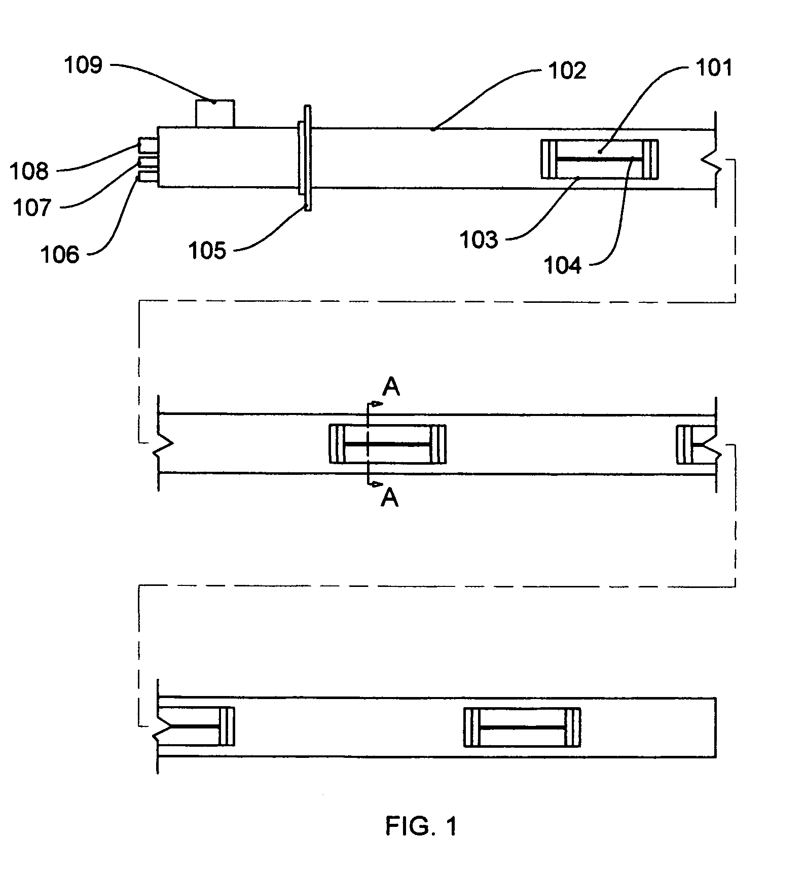
[0039]FIG. 1 illustrates a typical VGA nozzle-lance as assembled for installation in a flue gas duct and as utilized with injection of dry hydrated lime for SO2 capture. It is described herein by specific reference to FIG. 1. For the purpose of illustrating its length, typically about 20 ft., but generally ranging from the order of 10-30 ft., it is shown cut into three sections. Linear nozzles, 101 are located at suitable intervals within cylindrical tube / pipe lance 102 having rectangular windows 103 through which atomized spray issues from linear slits 104. Although, the illustration shows four nozzles, the number of nozzles and nozzle spacing may be varied to suit the flue gas duct size and capacity, with a general maximum of six nozzles per lance for uniformity of spray volume across a duct. The lance is fitted with pipe flange 105 for insertion through a duct wall. The inlet end is fitted with pipe fittings such as 106 for water feed, 107 for compressed, atomizing air, 108 for s...


PUM

PropertyMeasurementUnit
velocityaaaaaaaaaa
thicknessaaaaaaaaaa
thicknessaaaaaaaaaa

Abstract

Diverse methods of utilization and the corresponding, related modifications, of linear type, Variable Gas Atomization (VGA) nozzles and lances are described. Therein is joined the mixing and gas atomization of chemicals that react to form active products that further react with harmful flue gas constituents of combustion so as to enable their effective collection. One version combines, in a lance assembly of nozzles, the injection of reactants, in the form of finely divided dry solids conveyed in a carrier air stream, and the fine atomization of water, aqueous solutions or slurries. Atomization of such streams is employed to effectively wet the surfaces of the dry particles and, thereby, promote the rapid sorption of gaseous constituents of flue gas being treated. Another version simultaneously mixes and atomizes reacting chemicals to produce, and release into the flue gas stream, strongly oxidizing, transient, species of their reaction products. The simultaneous atomization and chemical reaction enables the effective capture of targeted flue gas constituents.

Description

CROSS REFERENCE TO RELATED APPLICATIONS[0001]This application claims the benefit of PPA Ser. No. 61 / 188,739 filed Aug. 12, 2008BACKGROUND OF THE INVENTION[0002]1. Field of the Invention[0003]This invention relates to methods and means for combining the mixing, reaction and compressed air atomization of reactive chemicals. It employs and expands upon the teachings of expired patent, “Variable Gas Atomization,” U.S. Pat. No. 4,314,670 (referred to herein as VGA), which was issued to this writer on Feb. 9, 1982. It comprises specific improvements to the atomizing nozzle configuration thereof that enable effective removal of harmful combustion gas stream constituents. It specifically relates to the removal of sulfur oxides, nitric oxides and mercury. It further relates to means of modification of conventional flue gas duct configuration so as to provide an effective and economical flue gas cleaning system via in-duct injection in existing utility, commercial and industrial power plants....

Claims


Application Information

Patent Timeline
Patent Type & Authority Patents(United States)
IPC IPC(8): B05B17/04B01D50/00B01D53/50B01D53/56B05B7/00B01D53/60B05B1/14B05B17/00
CPCB01D53/504B01D53/56B01D53/64B01D53/79B05B7/0815B05B1/044B05B1/205B01D2251/106B01D2257/302B01D2257/404B01D2257/602B01D2251/108
Inventor WALSH, JR., WILLIAM ARTHUR
Owner WALSH JR WILLIAM ARTHUR
Why Eureka
Try Eureka