Reducing transistor junction capacitance by recessing drain and source regions

a transistor and drain region technology, applied in the field of integrated circuit fabrication, can solve the problems of limited electrically effective dopant concentration, affecting the performance of transistors, and affecting the ability of the circuit to opera

Active Publication Date: 2010-07-13
CONVERSANT INTPROP MANAGEMENT INC
View PDF10 Cites 18 Cited by
  • Summary
  • Abstract
  • Description
  • Claims
  • Application Information

AI Technical Summary

Benefits of technology

[0012]Generally, the subject matter disclosed herein is directed to methods and semiconductor devices aiming at enhancing the transistor performance and reducing the overall transistor dimensions in SOI devices by reducing the thickness of a respective active semiconductor layer of the SOI device prior to forming respective deep drain and source regions. The respective process for the material removal may be performed at an appropriate manufacturing stage so as to provide the possibility of incorporating a strained semiconductor alloy in a preceding manufacturing stage, wherein the strained semiconductor alloy may be maintained along the depth direction in its initial thickness in the vicinity of the channel region when removing material from the drain and source areas. Consequently, the reduced thickness of the drain and source areas prior to the implantation of the deep drain and source regions enables the incorporation of the dopant species with high concentration so as to extend down to the buried insulating layer on the basis of efficient implantation parameters, thereby providing the potential for designing the respective anneal process for activating the dopants and re-crystallizing the drain and source regions in view of the desired lateral dopant profile rather than having to diffuse the dopants down to the buried insulating layer for obtaining a reduced junction capacitance. Consequently, the overall lateral transistor dimensions may be reduced compared to strategies using anneal parameters for inducing high diffusion activity, while nevertheless an efficient strain-inducing mechanism may be incorporated in the form of a strained semiconductor alloy in the drain and source regions.

Problems solved by technology

A key issue in developing integrated circuits of increased packing density and enhanced performance is the scaling of transistor elements, such as MOS transistor elements, to provide the great number of transistor elements that may be necessary for producing modern CPUs and memory devices.
Although the reduction of the gate length is necessary for obtaining smaller and faster transistor elements, it turns out, however, that a plurality of issues are additionally involved to maintain proper transistor performance for a reduced gate length.
One challenging task in this respect is the provision of shallow junction regions at least at the area in the vicinity of the channel region, i.e., source and drain extension regions, which nevertheless exhibit a high conductivity so as to minimize the resistivity in conducting charge carriers from the channel to a respective contact area of the drain and source regions.
The introduction of a high dose of dopants into a crystalline substrate area, however, generates heavy damage in the crystal structure and, therefore, one or more anneal cycles are typically required for activating the dopants, i.e., for placing the dopants at crystal sites, and to cure the heavy crystal damage.
However, the electrically effective dopant concentration is limited by the ability of the anneal cycles to electrically activate the dopants.
This ability in turn is limited by the solid solubility of the dopants in the silicon crystal and the temperature and duration of the anneal process that are compatible with the process requirements.
Moreover, besides the dopant activation and the curing of crystal damage, dopant diffusion may also occur during the annealing, which may lead to a “blurring” of the dopant profile.
In other areas of the drain and source regions, that is, in deeper lying portions, the diffusion may result in a reduction of the dopant concentration at the corresponding PN junction areas, thereby reducing the conductivity at the vicinity of theses areas.
Furthermore, very high temperatures during the anneal process may negatively affect the gate insulation layer, thereby reducing the reliability thereof.
That is, high anneal temperatures may degrade the gate insulation layer and thus may influence the dielectric characteristics thereof, which may result in increased leakage currents, reduced breakdown voltage and the like.
Thus, contrary to traditional rapid thermal anneal (RTA) processes, in which frequently the entire carrier material may be heated to a desired temperature, the 
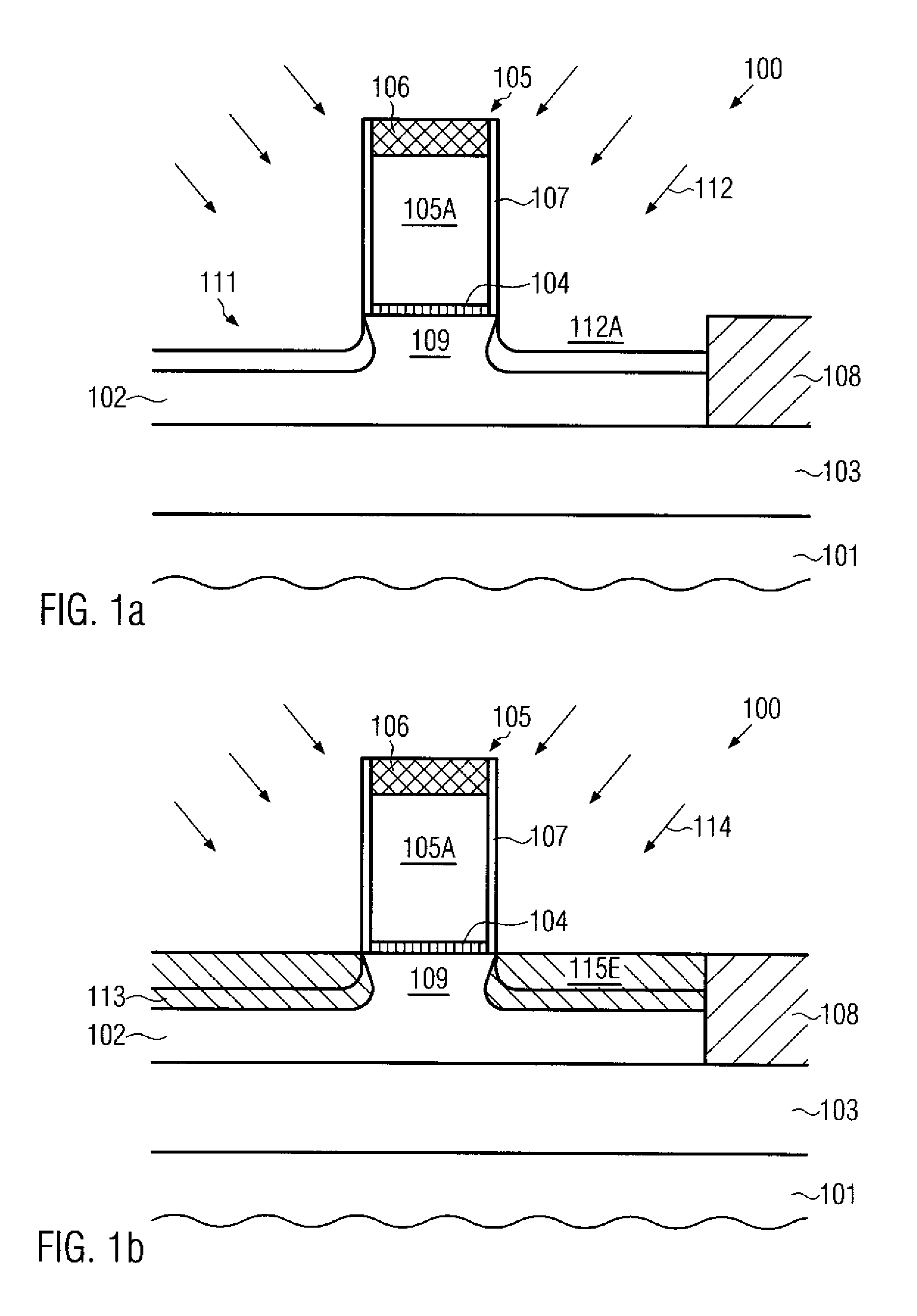
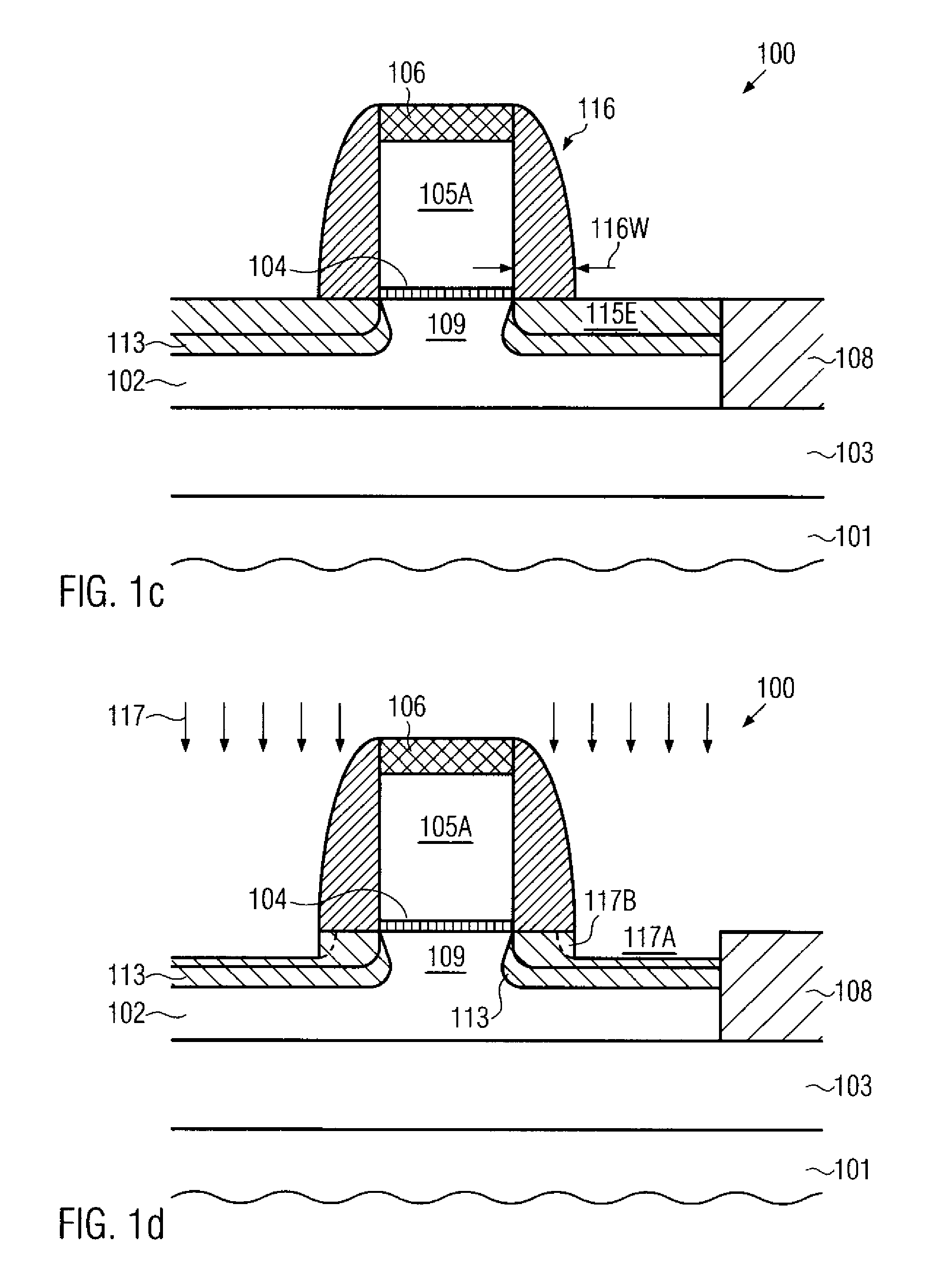
radiation-based advanced anneal techniques cause non-equilibrium conditions wherein a high amount of energy is supplied within extremely short time intervals, thereby providing the required extremely high temperatures at a very thin surface layer, while the remaining material of the substrate may remain substantially unaffected by the energy deposition during the anneal process.
However, adjusting the effective channel length on the basis of a well-controlled diffusion of the dopants may be difficult to be integrated in the conventional process flow unless significant efforts may be made, thereby resulting in additional process complexity.
However, providing deep drain and source regions with high dopant concentrations down to the buried insulating layer may require sophisticated implantation techniques, thereby contributing to the overall process complexity.
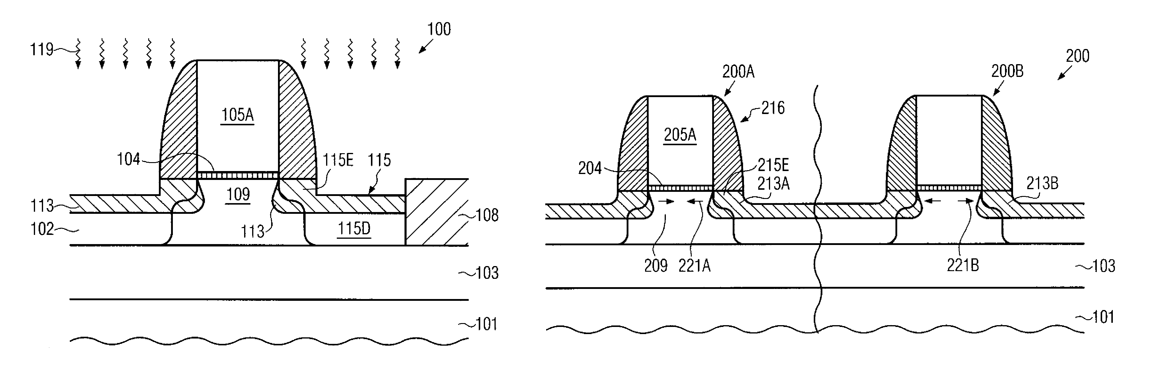
The respective anneal parameters may, however, not be compatible with the requirement of a reduced transistor length, since also a lateral diffusion, for instance in the extension regions, may take place and result in a modified channel length which may therefore require increased spacer widths to accommodate the increased diffusion activity during a respective anneal process.
Thus, high temperature anneal processes with extended process times for inducing high diffusion activity and thus generating a high thermal budget may be a less attractive approach in view of increasing the packing density of sophisticated semiconductor devices.

Method used


Image

  • Reducing transistor junction capacitance by recessing drain and source regions
  • Reducing transistor junction capacitance by recessing drain and source regions
  • Reducing transistor junction capacitance by recessing drain and source regions

Examples


Embodiment Construction

[0023]Various illustrative embodiments of the invention are described below. In the interest of clarity, not all features of an actual implementation are described in this specification. It will of course be appreciated that in the development of any such actual embodiment, numerous implementation-specific decisions must be made to achieve the developers' specific goals, such as compliance with system-related and business-related constraints, which will vary from one implementation to another. Moreover, it will be appreciated that such a development effort might be complex and time-consuming, but would nevertheless be a routine undertaking for those of ordinary skill in the art having the benefit of this disclosure.

[0024]The present subject matter will now be described with reference to the attached figures. Various structures, systems and devices are schematically depicted in the drawings for purposes of explanation only and so as to not obscure the present disclosure with details ...


PUM


Abstract

By recessing portions of the drain and source areas on the basis of a spacer structure, the subsequent implantation process for forming the deep drain and source regions may result in a moderately high dopant concentration extending down to the buried insulating layer of an SOI transistor. Furthermore, the spacer structure maintains a significant amount of a strained semiconductor alloy with its original thickness, thereby providing an efficient strain-inducing mechanism. By using sophisticated anneal techniques, undue lateral diffusion may be avoided, thereby allowing a reduction of the lateral width of the respective spacers and thus a reduction of the length of the transistor devices. Hence, enhanced charge carrier mobility in combination with reduced junction capacitance may be accomplished on the basis of reduced lateral dimensions.

Description

BACKGROUND OF THE INVENTION[0001]1. Field of the Invention[0002]The present disclosure generally relates to the fabrication of integrated circuits, and, more particularly, to the fabrication of highly sophisticated field effect transistors, such as MOS transistor structures in SOI configuration, having highly doped junctions with reduced junction capacitance.[0003]2. Description of the Related Art[0004]The manufacturing process for integrated circuits continues to improve in several ways, driven by the ongoing efforts to scale down the feature sizes of the individual circuit elements. Presently, and in the foreseeable future, the majority of integrated circuits are, and will be, based on silicon devices due to the high availability of silicon substrates and due to the well-established process technology that has been developed over the past decades. A key issue in developing integrated circuits of increased packing density and enhanced performance is the scaling of transistor elemen...

Claims


Application Information

Patent Timeline
Patent Type & Authority Patents(United States)
IPC IPC(8): H01L21/8238H01L21/425H01L29/80H01L27/10H01L21/336
CPCH01L21/324H01L21/84H01L27/1203H01L29/41733H01L29/6659H01L29/66628H01L29/66636H01L29/66772H01L29/7848H01L29/78621H01L21/26506H01L21/26513H01L21/26586H01L21/823807H01L21/823814H01L21/823878H01L29/665
Inventor FEUDEL, THOMASLENSKI, MARKUSGEHRING, ANDREAS
Owner CONVERSANT INTPROP MANAGEMENT INC
Why Eureka
Try Eureka