
Heat spreader having single layer of diamond particles and associated methods

a diamond particle and heat spreader technology, applied in semiconductor devices, lighting and heating apparatus, semiconductor/solid-state device details, etc., can solve the problems of insufficient cooling of future generations of cpus, insufficient heat dissipation methods, and neglect of design phase, and achieve the effect of cementing diamond particles

Inactive Publication Date: 2010-09-07
RITEDIA CORPORATION
View PDF99 Cites 28 Cited by
  • Summary
  • Abstract
  • Description
  • Claims
  • Application Information

AI Technical Summary

Benefits of technology

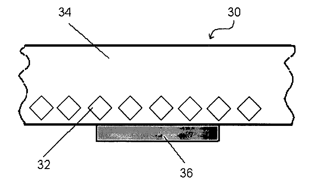
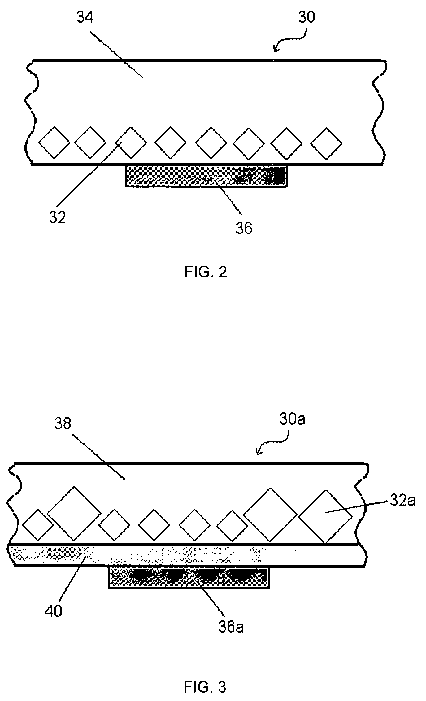
[0016]Accordingly, the present invention provides heat spreaders that can be used to draw or conduct heat away from a heat source. In one aspect, a heat spreader includes a plurality of diamond particles arranged in a single layer and surrounded by a metallic mass. The single layer of diamond particles can be a single particle thick. The metallic mass can effectively cement the diamond particles and can be free of substantially all diamond particles besides those present in the single layer. In another variation of a heat spreader, a single layer of diamond particles can be a single layer thick, with each diamond particle in direct physical contact with another diamond particle. A metallic mass can cement the diamond particles together on at least one side of the heat spreader.
[0017]A thermal management system is also presented. The system includes a heat source and a heat spreader in contact with the heat source. The heat spreader can have a first and second side, oppositely located. The first side can have a lower thermal expansion and higher thermal conductivity than the second side. The single layer of cemented diamond particles in the heat spreader can affect such properties. The single layer of diamond particles can be a single particle thick. Furthermore, there can be substantially no other diamond particles in the heat spreader beyond those present in the single layer. The first side of the heat spreader can be closer to the heat source than the second side, thus allowing for better contact with the heat source, preferable long-term performance characteristics, and the ability to efficiently remove heat from the heat source.

Problems solved by technology

Along with such advances comes various design challenges.
One of the often overlooked challenges is that of heat dissipation.
Most often, this phase of design is neglected or added as a last minute design before the components are produced.
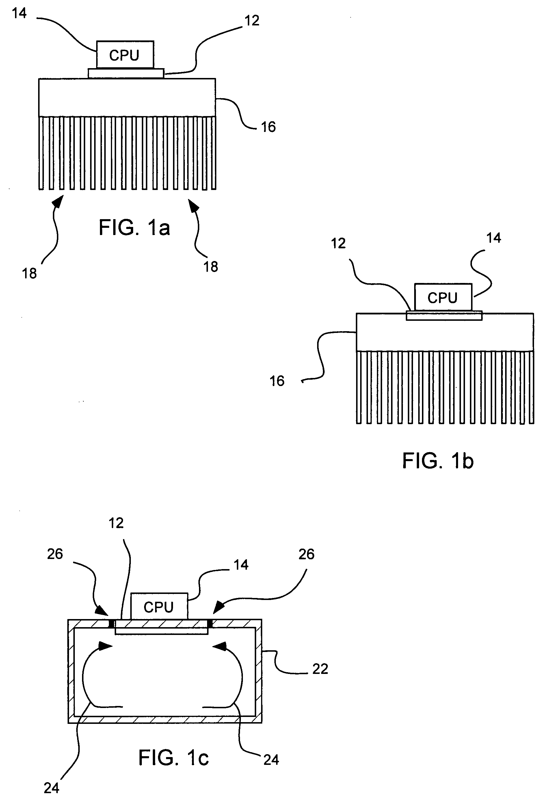
Current methods of heat dissipation, such as by using metal (e.g., Al or Cu) fin radiators, and water evaporation heat pipes, will be inadequate to sufficiently cool future generations of CPUs.
However, such materials have a thermal conductivity that is no greater than that of Cu, hence, their ability to dissipate heat from semiconductor chips is limited.
When the chip is heated to above 60° C., the mismatch of thermal expansions between metal and ceramics can create microcracks.
The repeated cycling of temperature tends to aggravate the damage to the chip.
As a result, the performance of the semiconductor will deteriorate.
Moreover, when temperatures reach more than 90° C., the semiconductor portion of the chip may become a conductor so the function of the chip is lost.
In addition, the circuitry may be damaged and the semiconductor is no longer usable (i.e. becomes “burned out”).
Although heat pipes and heat plates may remove heat very efficiently, the complex vacuum chambers and sophisticated capillary systems prevent designs small enough to dissipate heat directly from a semiconductor component.
As a result, these methods are generally limited to transferring heat from a larger heat source, e.g., a heat sink.
However, large area diamonds are very expensive; hence, diamond has not been commercially used to spread the heat generated by CPUs.
This high price would prohibit diamond heat spreaders from being widely used except in those applications (e.g., high power laser diodes) where only a small area is required or no effective alternative heat spreaders are available.
In addition to being expensive, CVD diamond films can only be grown at very slow rates (e.g., a few micrometers per hour); hence, these films seldom exceed a thickness of 1 mm (typically 0.3-0.5 mm).
Such PCD compacts are of limited use in the field of heat spreaders because of their limited physical capacity to transfer or conduct heat.

Method used


Image

  • Heat spreader having single layer of diamond particles and associated methods
  • Heat spreader having single layer of diamond particles and associated methods
  • Heat spreader having single layer of diamond particles and associated methods

Examples


example 1

Method of Making a Heat Spreader

[0087]Diamond particles of 30 / 40 U.S. mesh (Element Six SDB 1100) are thoroughly cleaned in acetone with ultrasonic vibration. A steel tray is fitted with a 100 micron film of deoxidized copper. A double sticking adhesive 25 microns thick is attached to the copper film. Diamond particles are spread onto the top of the adhesive layer and agitated by ultrasonic vibrations to increase the packing efficiency. The tray is overturned to discard diamond particles that are not stuck to the adhesive. Once loose particles are discarded, the tray is turned right side up again. A 2 mm thick plate of pure aluminum is placed on top of the diamond particles. The arrangement is illustrated in FIG. 5a, wherein the copper layer with adhesive 46 has a layer of diamond particles 48 covered by a plate of aluminum 50. The tray is then placed in a vacuum furnace and heated to 680° C. The aluminum infiltrates between the gaps of the diamond particles. The tray is allowed to ...

example 2

Method of Making Multiple Heat Spreaders

[0088]The process of Example 1 is followed, except that strips of copper are laid down over the adhesive layer prior to introducing diamond particles. The strips can be adjusted to create 20 mm squares of exposed adhesive.

[0089]Once the tray is allowed to cool, the aluminum top is ground smooth and the plate is wire-EDM cut along the middle lines of the copper stripe dividers. This produces multiple heat spreaders of about 40 mm. Each square contains about 1600 crystals (about 4 carats, at an approximate cost of 80 cents), with flat faces firmly embedded in the copper film. FIG. 6 illustrates an exemplary plate 52 of multiple heat spreaders prior to cutting, in accordance with the present example. The copper strips (covered with aluminum) 54, separate the individual heat spreaders 56 which include a single diamond layer.

[0090]Such heat spreaders can be soldered directly to a computer chip and / or soldered onto a heat sink or a heat pipe. The th...

example 3

Heat Spreader with Silicon

[0091]Same as Example 1, except molten silicon is used in place of aluminum, and infiltration is done at 1450° C. The final product is an electrical insulator as opposed to the electrically conductive copper. Additionally, the composite thermal expansion coefficient is smaller than in Example 1.

[0092]If excessive diffusion takes place at the interface of the infiltrant and the copper film, the thermal conductivity can be reduced. Additionally, the thin copper film can be dissolved. In this case, a flash of a more refractory metal can be coated on the copper film to become a chemical barrier. For example, tungsten can be sputtered onto the copper film. The thermal conductivity of tungsten is not low and it is very thin (e.g. nanometers), so the thermal resistance can be negligible.


PUM

PropertyMeasurementUnit
temperatureaaaaaaaaaa
pressuresaaaaaaaaaa
poweraaaaaaaaaa

Abstract

A heat spreader is presented which can provide effective thermal management in a cost effective manner. The heat spreader includes a plurality of diamond particles arranged in a single layer surrounded by a metallic mass. The metallic mass cements the diamond particles together. The layer of diamond particles is a single particle thick. Besides the single layer of diamond particles, the metallic mass has substantially no other diamond particles therein. A thermal management system including a heat source and a heat spreader is also presented, along with methods for making and methods for use of such heat spreaders.

Description

FIELD OF THE INVENTION[0001]The present invention relates to carbonaceous composite devices and methods for conducting or absorbing heat away from a heat source. Accordingly, the present invention involves the fields of chemistry, physics, semiconductor technology, and materials science.BACKGROUND OF THE INVENTION[0002]Progress in the semiconductor industry has been following the trend of Moore's Law that was proposed in 1965 by then Intel's cofounder Gordon Moore. This trend requires that the capability of integrated circuits (IC) or, in general, semiconductor chips double every 18 months.[0003]Along with such advances comes various design challenges. One of the often overlooked challenges is that of heat dissipation. Most often, this phase of design is neglected or added as a last minute design before the components are produced. According to the second law of thermodynamics, the more work that is performed in a closed system, the higher entropy it will attain. With the increasing...

Claims


Application Information

Patent Timeline
Patent Type & Authority Patents(United States)
IPC IPC(8): H01L23/10H01L23/34
CPCH01L23/3732F28F21/08H01L2924/0002H01L2924/00
Inventor SUNG, CHIEN-MIN
Owner RITEDIA CORPORATION
Learn More