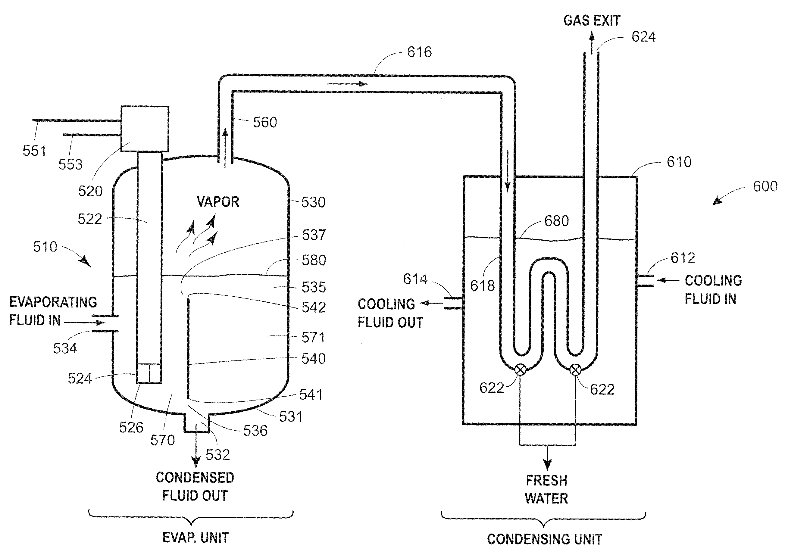
Desalination system

a desalination system and liquid technology, applied in the direction of filtration separation, machine/engine, separation process, etc., can solve the problems of flash vaporization system corrosion and erosion problems, large energy requirements of methods, and frequent replacement of components, so as to reduce the degree of mixing, the effect of clogging and fouling associated with other evaporators, and high degree of turbulen

Active Publication Date: 2010-11-16
HEARTLAND WATER TECH INC
View PDF86 Cites 60 Cited by
  • Summary
  • Abstract
  • Description
  • Claims
  • Application Information

AI Technical Summary

Benefits of technology

[0013]During operation, gas introduced through the tube or tubes mixes with the evaporative fluid in a first confined volume formed by the weir or the weir and a wall of the evaporation vessel and the tube(s) and the fluid mixture of gas and liquid flows at high volume with a high degree of turbulence along the circulation path defined around the weir(s), thereby causing a high degree of mixing between the gas and the evaporative fluid and any suspended particles within the evaporative fluid. Shear forces within this two-phase or three-phase turbulent flow region that result from the high density liquid phase overrunning the low density gas phase create extensive interfacial surface area between the gas and the evaporative fluid that favors minimum residence time for mass and heat transfer between the liquid and gas phases to come to equilibrium compared to conventional gas dispersion techniques. Still further, vigorous mixing created by the turbulent flow hinders the formation of large crystals of precipitates within the evaporative fluid and, because the system does not use small holes or other ports to introduce the gas into the evaporative fluid, clogging and fouling associated with other evaporators are significantly reduced or entirely eliminated. Still further, the predominantly horizontal flow direction of the liquid and gas mixture over the top of the weir and along the surface of the evaporative fluid within the evaporation vessel enables the gas phase to disengage from the process fluid with minimal entrainment of liquid due to the significantly greater momentum of the much higher density liquid that is directed primarily horizontally compared to the low density gas with a relatively weak but constant vertical momentum component due to buoyancy.
[0014]In addition, a method of desalination using a submerged gas evaporator includes providing a evaporative fluid to an evaporator vessel of a submerged gas evaporator at a rate sufficient to maintain the evaporative fluid level at a predetermined level within the evaporator vessel, supplying a gas to the evaporator vessel, and mixing the gas and evaporative fluid within the evaporator vessel by causing the gas and evaporative fluid to flow around a weir or weirs within the submerged gas processor to thereby transfer heat energy and mass between the gas and liquid phases of a mixture.

Problems solved by technology

Both of these methods have large energy requirements and certain components that wear out frequently.
For example, reverse osmosis systems force water through membranes and these membranes become clogged and torn, thus necessitating frequent replacement.
Similarly, flash vaporization systems have corrosion and erosion problems due to the spraying of hot brine within these systems.
Due to the high energy inputs and frequent maintenance, desalination of water on a large scale basis has been relatively expensive, often more expensive than finding alternate sources of groundwater.
However, during the evaporation process, dissolved solids within the continuous liquid phase become more concentrated often leading to the formation of precipitates that are difficult to handle.
Biological growth leads to the formation of slime within a desalination system that further reduces desalination efficiency and can also foul heat exchangers within equipment which employs the circulating liquid from the desalination system as an evaporative medium.
These common problems adversely affect the efficiency and costs of conventional desalination systems in that they necessitate frequent cleaning cycles and / or the addition of chemical control agents to the evaporative fluid to avoid loss of efficiency and to avoid sudden failures within the evaporation equipment.
Additionally, most evaporation systems that rely on intimate contact between gases and liquids are prone to problems related to carryover of entrained liquid droplets that form as the vapor phase disengages from the liquid phase.
Droplets within the vapor are particularly troublesome if the process is applied to produce potable water in that the entrained droplets contain the salts, minerals and other contaminants that were in the feed liquid.
Submerged gas evaporators also tend to mitigate the formation of large crystals because dispersing the gas beneath the liquid surface promotes vigorous agitation within the evaporation vessel, which is a less desirable environment for crystal growth than a more quiescent zone.
However, mitigation of crystal growth and settlement is dependent on the degree of mixing achieved within a particular submerged gas evaporator, and not all submerged gas evaporator designs provide adequate mixing to prevent large crystal growth and related blockages.
Therefore, while the dynamic renewable heat transfer surface area feature of submerged gas evaporators eliminates the potential for fouling liquids to coat extended surfaces, conventional submerged gas evaporators are still subject to potential blockages and carryover of entrained liquid within the exhaust gas flowing away from the evaporation zone.

Method used


Image

  • Desalination system
  • Desalination system
  • Desalination system

Examples


Embodiment Construction

[0022]The performance of desalination systems according to the disclosure depends on the moisture content and temperature of the gas and the thermodynamic properties of the evaporative fluid, which are usually ambient air and water. As with conventional desalination systems, equations developed by Merkel that are based the enthalpy potential difference between the evaporative fluid and air, may be used to closely define the performance of a desalination system that is constructed according to the invention for a particular application. Desalination systems according to the disclosure can be substituted for conventional desalination systems. Conventional means of controlling the flow of evaporative fluid through the desalination system may be employed. Likewise, conventional means of controlling desalination systems to meet the requirements of a particular desalination system application may be employed. Multiple desalination systems according to the invention may be connected in ser...


PUM

PropertyMeasurementUnit
energyaaaaaaaaaa
diametersaaaaaaaaaa
diametersaaaaaaaaaa

Abstract

A desalination system in the form of a submerged gas evaporator that includes a vessel, a gas delivery tube partially disposed within the vessel to deliver a gas into the vessel and a fluid inlet that provides a fluid to the vessel at a rate sufficient to maintain a controlled constant level of fluid within the vessel. A weir is disposed within the vessel adjacent the gas delivery tube to form a first fluid circulation path between a first weir end and a wall of the vessel and a second fluid circulation path between a second weir end and an upper end of the vessel. During operation, gas introduced through the tube mixes with the fluid and the combined gas and fluid flow at a high rate with a high degree of turbulence along the first and second circulation paths defined around the weir, thereby promoting vigorous mixing and intimate contact between the gas and the fluid. This turbulent flow develops a significant amount of inter facial surface area between the gas and the fluid resulting in a reduction of the required residence time of the gas within the fluid to achieve thermal equilibrium which leads to a more efficient and complete evaporation. Additionally, vapor exiting the submerged gas evaporator is condensed in a condensing unit thus precipitating vapor into a liquid for removal.

Description

FIELD OF THE DISCLOSURE[0001]The present disclosure relates generally to desalination systems and liquids, and more specifically, to desalination systems including submerged gas evaporators.BACKGROUND[0002]Desalination systems are systems that remove salt or other dissolved solids from water, most often to produce potable water. Currently, several methods of desalination are employed by commercial desalination systems. The most popular methods of commercial desalination are reverse osmosis and flash vaporization. Both of these methods have large energy requirements and certain components that wear out frequently. For example, reverse osmosis systems force water through membranes and these membranes become clogged and torn, thus necessitating frequent replacement. Similarly, flash vaporization systems have corrosion and erosion problems due to the spraying of hot brine within these systems. The energy requirements for a reverse osmosis system may be approximately 6 kWh of electricity...

Claims


Application Information

Patent Timeline
Patent Type & Authority Patents(United States)
IPC IPC(8): B01F3/04
CPCB01D1/0058B01D1/14B01D1/305B01D5/0006C02F1/10C02F1/14B01D5/006C02F2301/024C02F2101/12C02F2103/08Y02A20/124
Inventor DUESEL, JR., BERNARD F.RUTSCH, MICHAEL J.
Owner HEARTLAND WATER TECH INC
Why Eureka
Try Eureka