Quasi-parallel voltage regulator

a voltage regulator and parallel-parallax technology, applied in the direction of electric variable regulation, process and machine control, instruments, etc., can solve the problems of compromising accurate voltage control, difficult to accommodate, and generally present loads which are the most demanding to accommodate, so as to achieve small size, and high current slew rate

Inactive Publication Date: 2011-01-18
VIRGINIA TECH INTPROP INC
View PDF6 Cites 44 Cited by
  • Summary
  • Abstract
  • Description
  • Claims
  • Application Information

AI Technical Summary

Benefits of technology

[0010]It is therefore an object of the present invention to provide a power supply architecture which can provide high current at low and well-regulated voltage while accommodating large load transients and providing high current slew rate and which can be realized at small size and weight at low cost.

Problems solved by technology

Among such devices, microprocessors and other high-speed logic circuits generally present loads which are most demanding to accommodate.
Many of these requirements and desirable features impose conflicting constraints on design or require trade-offs which may be very difficult to accommodate.
For example, accommodation of high current slew rate can be achieved with large output filter capacitance but which may compromise accurate voltage control and increase size, weight and cost of the power supply.
Similarly, the requirement for lower power supply output voltages generally compromises efficiency since a lower output voltage generally increases the voltage step-down which must be achieved by a DC to DC converter while very sophisticated power supply designs are required to achieve even very small increases in efficiency.
On the other hand, some voltage converter or transformer designs are known which may be of characteristically very high efficiency but cannot achieve other desired characteristics while maintaining such efficiency or presenting intractable design problems.
However, since the two stages are in series in this design, each stage must be designed to handle the full power load and thus efficiency is compromised during operation at low load which, for microprocessors in particular, can be a substantial fraction of the total operating time.
Consequently, the fully parallel power supply architecture of FIG. 2 cannot accommodate rapid load transients and high current slew rates which are typical of loads presented by microprocessors.
Thus, in summary, while many voltage regulator topologies are known and power supply architectures have become quite sophisticated, such designs are far from ideal for the types of loads presented by some current and foreseeable applications, particularly those including microprocessors.
The effects of trade-offs necessary to accommodate the many demands of such applications are particularly severe and increasing in severity as present trends in integrated circuit designs continue.

Method used


Image

  • Quasi-parallel voltage regulator
  • Quasi-parallel voltage regulator
  • Quasi-parallel voltage regulator

Examples


Embodiment Construction

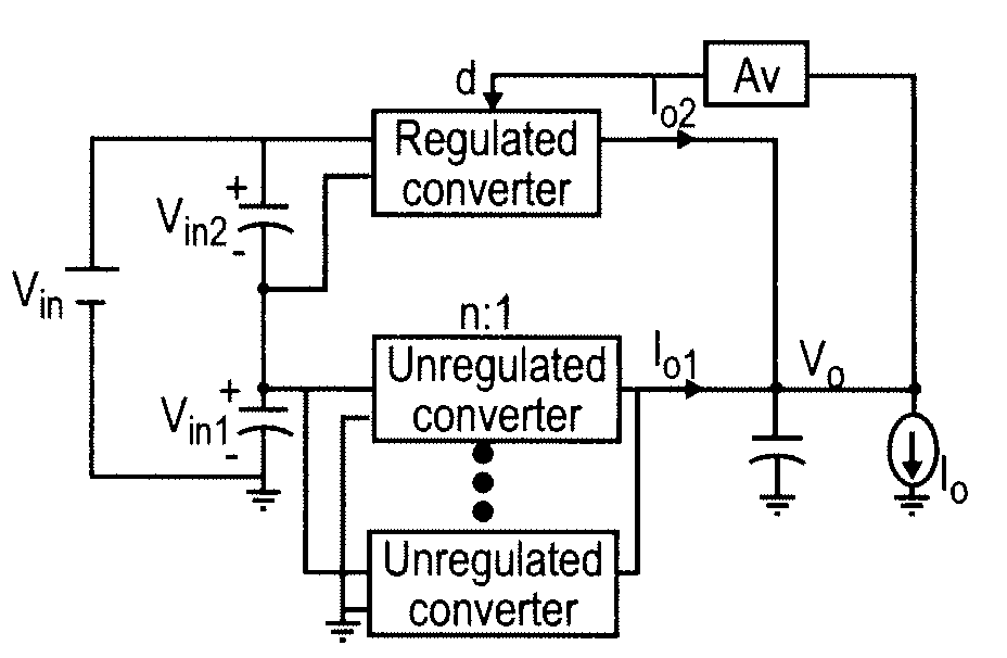
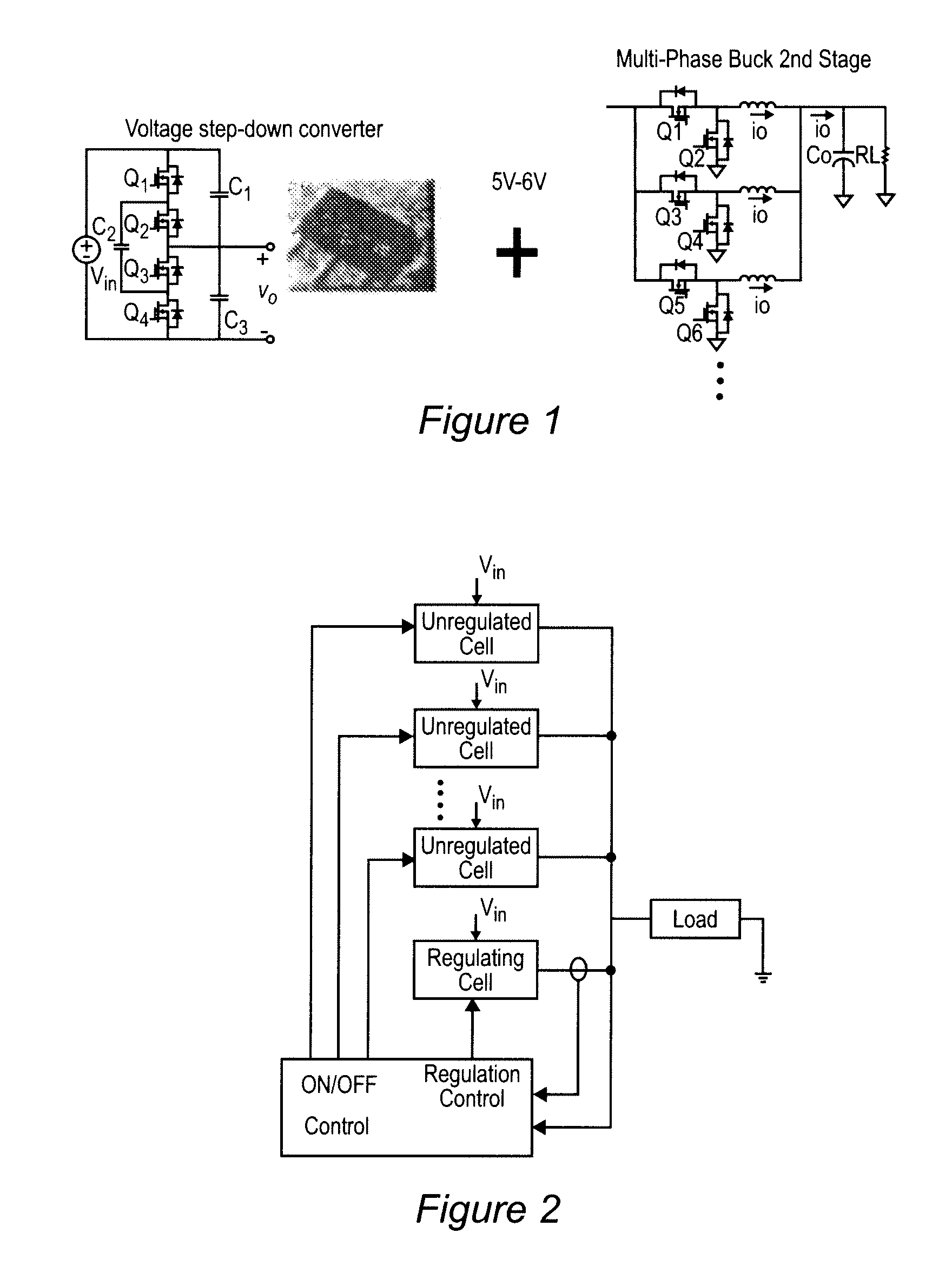
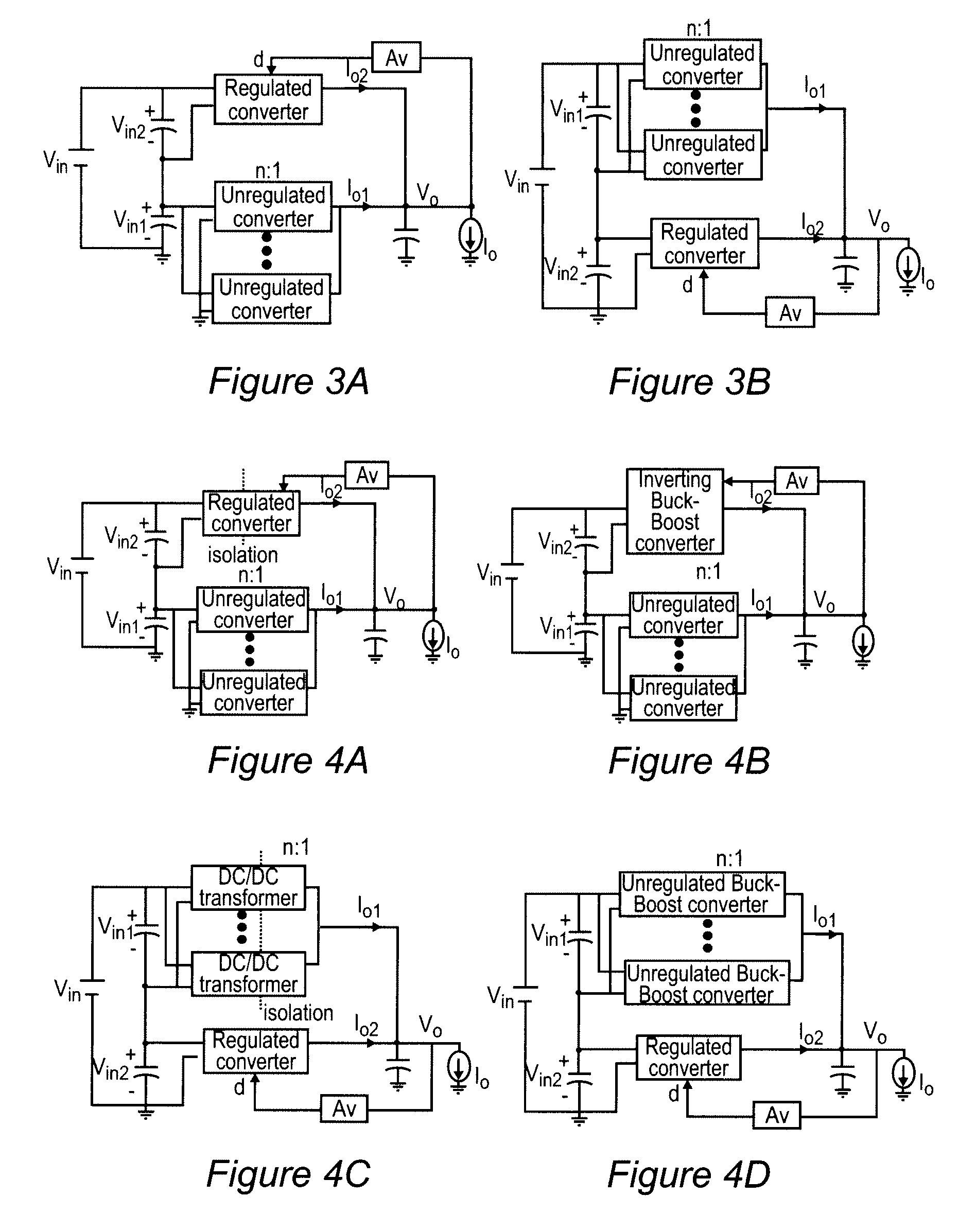
[0034]Referring now to the drawings, and more particularly to FIGS. 3A and 3B, block diagrams of the quasi-parallel architecture of a voltage regulator in accordance with the invention are shown. The circuit topologies shown in FIGS. 3A and 3B are identical; FIG. 3B being inverted top-to-bottom relative to FIG. 3A. It will be immediately recognized that the circuit architecture of FIGS. 3A and 3B differs from that of FIG. 1 in that the unregulated converters or cells are connected in parallel rather than in series, much in the fashion illustrated in FIG. 2. However, as compared with FIG. 2, the circuit architecture of the invention further differs from a fully parallel architecture such as that of FIG. 2 by supplying the input to the regulated and unregulated converters or cells from capacitors which are connected in series across the input voltage source Vin and thus function as two separate input sources providing voltages which are generally unequal but which total Vin. As will b...


PUM


Abstract

Improved regulation and transient response are provided by a power supply architecture providing both unregulated and regulated voltage converters in parallel but deriving input power from separate power supplies connected in series wherein regulated and unregulated branches each provide a substantially fixed and constant proportion of the output current. The series connection of input power sources may provide a further feedback mechanism in addition to feedback for regulation which enhances overall performance. As a perfecting feature of the invention, inductor-less resonant converters which are switched in an interleaved fashion may be used in the unregulated branch while substantially cancelling the characteristic large output voltage ripple thereof.

Description

BACKGROUND OF THE INVENTION[0001]1. Field of the Invention[0002]The present invention generally relates to voltage regulator circuits / modules and, more particularly, to providing regulated voltage to loads at high current and low voltage with fast transient load response capability and circuits capable of doing so.[0003]2. Description of the Prior Art[0004]Many commercially available electronic devices require power at a well-regulated, substantially constant or well-defined voltage for proper operation. Among such devices, microprocessors and other high-speed logic circuits generally present loads which are most demanding to accommodate.[0005]Current trends in designs for microprocessors have featured increased levels of integration of circuitry on a single chip and the use of higher clock speeds. These design trends have also led to lower (e.g. one volt or less) and more stringent and / or complex voltage regulation requirements (e.g. 10% or less, possibly with specified voltage dro...

Claims


Application Information

Patent Timeline
Patent Type & Authority Patents(United States)
IPC IPC(8): H02M7/00
CPCH02M3/1584H02M2001/0074Y02B70/1425H02M1/0074Y02B70/10
Inventor XU, MINGSUN, JULULIU, YALEE, FRED C.
Owner VIRGINIA TECH INTPROP INC
Why Eureka
Try Eureka