Processes for the production of electrophoretic displays

Active Publication Date: 2011-03-22
E INK CORPORATION
View PDF282 Cites 174 Cited by
  • Summary
  • Abstract
  • Description
  • Claims
  • Application Information

AI Technical Summary

Problems solved by technology

Nevertheless, problems with the long-term image quality of these displays have prevented their widespread usage.
For example, particles that make up electrophoretic displays tend to settle, resulting in inadequate service-life for these displays.
Such gas-based electrophoretic media appear to be susceptible to the same types of problems due to particle settling as liquid-based electrophoretic media, when the media are used in an orientation which permits such settling, for example in a sign where the medium is disposed in a vertical plane.
Indeed, particle settling appears to be a more serious problem in gas-based electrophoretic media than in liquid-based ones, since the lower viscosity of gaseous suspending fluids as compared with liquid ones allows more rapid settling of the electrophoretic particles.
However, as already mentioned these prior art techniques are not satisfactory for forming, on arbitrary three-dimensional shapes, electrophoretic medium coatings with a sufficiently uniform thickness to give optimum optical performance.
While coating methods such as dip or spray coating can be applied to arbitrary three-dimensional shapes, it is difficult to or impossible to achieve uniform capsule monolayers over the substrate surface using these coating techniques.
Other problems encountered with slot coating techniques include:(a) chatter-like streaks parallel to the coating head (for example, due to vibrations in the coating apparatus); these streaks are believed to result from periodic bunching or jamming of capsules;(b) streaking in the direction of coating (i.e., perpendicular to the slot of the coating head), believed to be due to capsule jamming or non-uniform flows in delivery of capsules to the coating head;(c) less than desirable capsule contact (or wetting) with the optical face due to inadequate settling or deformability of the small capsules (of the order of 20-200 μm) typically used in encapsulated electrophoretic displays; and(d) non-uniformities in coating thickness due to formation of multiple layers of capsules (see the aforementioned U.S. Pat. No. 6,839,158 for a discussion of the advantages of forming only a single layer of capsules on a substrate).
The presence of these types of defects can adversely affect the appearance and optical performance of the display.
Also, as is well known to those skilled in slot coating technology, slot coating imposes limitations upon the viscosity and other physical properties of the material being coated, and typically requires the addition of slot coating additives to control the rheology of the coated material to ensure that the coating does not flow and develop non-uniformities in thickness prior to drying.
Although the binder serves several useful functions, including ensuring adequate adhesion of the capsule film to the substrate on which it is coated, excessive amounts of binder can hinder capsule contact with the electrode which is normally present on the substrate, and may also hinder the desirable flattening of the faces of the capsules in contact with the conductive coating (see, for example, the aforementioned U.S. Pat. No. 6,067,185).
Because the binder typically has a substantial effect on the viscosity and other physical properties of the capsule / binder mixture, at least in some cases it may be difficult to reduce the amount of binder used and still maintain these physical properties at values compatible with slot coating.
However, while conventional printing techniques might be used to prepare large displays of this type having resolutions of (say) less than 10 lines per inch (approximately 0.4 lines per mm), producing high resolution displays of this type with resolutions of about 100 lines per inch (approximately 4 lines per mm) with such conventional techniques is very difficult.
Again, while spray or ink jet coating might be used to apply the patterned coatings of capsules, producing monolayer capsule coatings using these methods will be difficult or impossible.
Switching between two colors (red plus blue, for example) is not possible in this type of display.

Method used


Image

  • Processes for the production of electrophoretic displays
  • Processes for the production of electrophoretic displays
  • Processes for the production of electrophoretic displays

Examples


example 1

Electrophoretic Deposition of Microcapsules

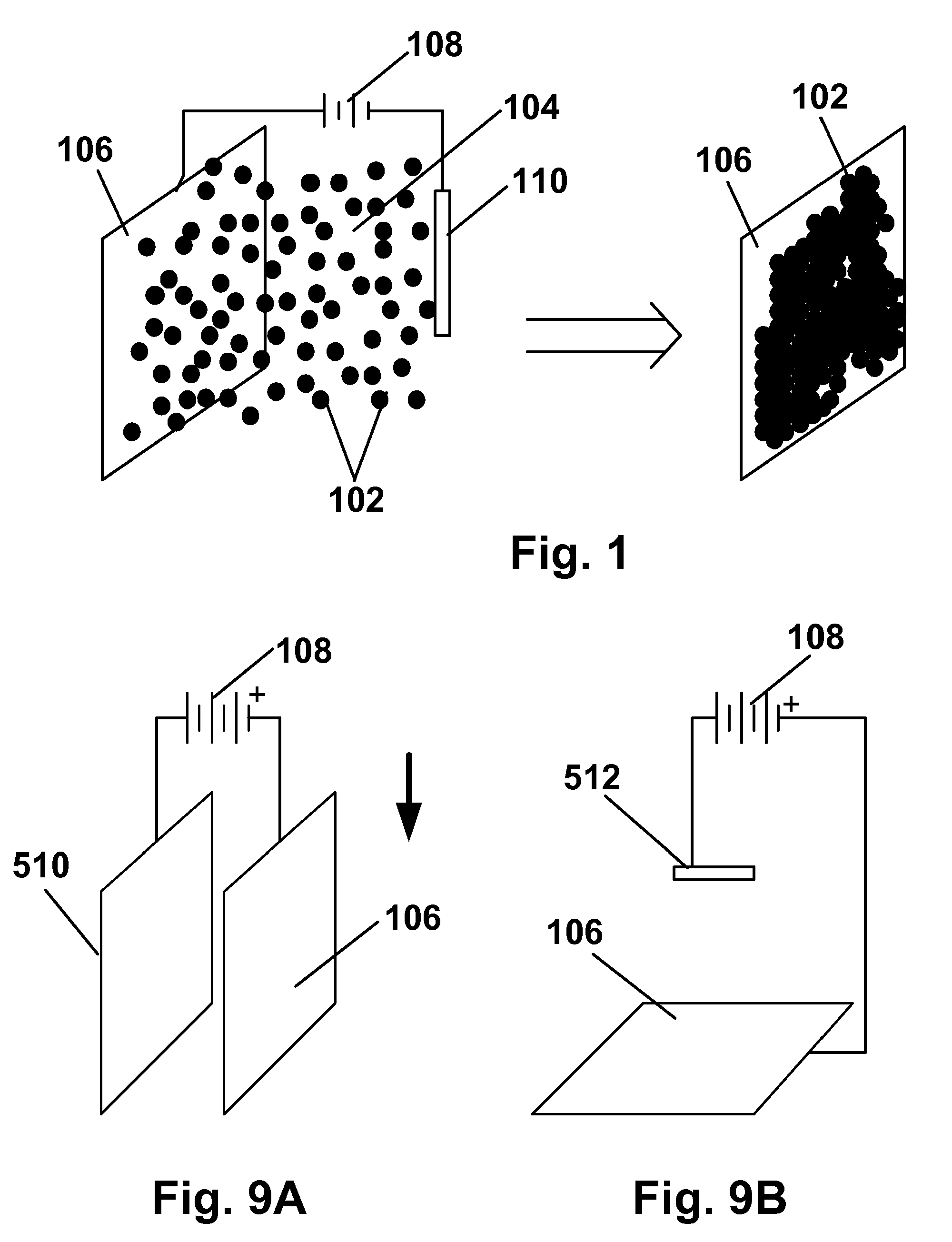
[0159]Preliminary experiments were conducted to determine the zeta potential of several different gelatin coacervates in water (coacervate nomenclature: GA=gelatin-acacia, G-PAA=gelatin-polyacrylic acid, G-HMP=gelatin-hexametaphosphate) as a function of pH and the results are shown in FIG. 10. For the GA coacervate, it was found that, as pH increased, coacervates formed from equal weights of gelatin and acacia become increasingly negatively charged. It appeared likely that adjusting the ratio of gelatin to acacia would affect the pH of zero charge, approximately 3.5 for the GA shown in FIG. 10, and also the plateau value of zeta potential at high pH.

[0160]Electrophoretic deposition experiments were then conducted using the vertical apparatus of FIG. 9A with glass coated with ITO (glass / ITO) for both the substrate and counter-electrode and capsule slurries with 0.05cb=0). At low pH (5.5, capsules were found to deposit only on the positive su...

example 2

Effect on Deposition of Electrode Material

[0162]The electrophoretic deposition experiments of Example 1 were repeated using glass / ITO, poly(ethylene terephthalate) (PET) / ITO, platinum, chrome, and copper substrates. In all cases, coatings were achieved by adjusting slurry pH and / or the encapsulation conditions, but all coatings without binder were typically limited to less than monolayer coverages of 65-80% after washing. This list of electrode materials on to which capsules can be electrophoretically deposited and adhered is not comprehensive; many more materials could presumably be coated by adjusting slurry pH, or capsule chemistry to promote the electrochemistry with a particular surface material that results in adhesion. The surfaces used were not intentionally patterned in any way to aid deposition; however, it was observed that in some cases apparent defects on the surface were preferentially coated with capsules (fabrication of patterned coatings is discussed in Example 9 be...

example 3

Electrochemical Degradation

[0163]As already noted significant electrochemical degradation of the positive electrode (deposition substrate) was observed to occur with certain electrode materials; this was most evident with substrates where a very thin conductive layer was deposited onto a nonconductive support, for example ITO on PET or chrome on glass. It was found that significant electrode degradation could interrupt the deposition process or cause highly laterally non-uniform coatings to develop. Generally as deposition proceeds, for example at constant voltage, electrochemical degradation can be recognized as a rapid decrease in current (vice versa for constant current conditions). Note that at constant current (with a suitable high voltage current source) deposition and electrochemical process proceed until the electrode fails catastrophically, whereas at constant voltage, the deposition process and degradation slow down as the experiment proceeds because the current drops off....


PUM

PropertyMeasurementUnit
conductivityaaaaaaaaaa
widthaaaaaaaaaa
pHaaaaaaaaaa

Abstract

A coating of an encapsulated electrophoretic medium is formed on a substrate (106) by dispersing in a fluid (104) a plurality of electrophoretic capsules (102), contacting at least a portion of a substrate (106) with the fluid (104); and applying a potential difference between at least a part of the portion of the substrate (106) contacting the fluid (104) and a counter-electrode (110) in electrical contact with the fluid (104), thereby causing capsules (102) to be deposited upon at least part of the portion of the substrate (106) contacting the fluid (102). Patterned coatings of capsules containing different colors may be deposited in registration with electrodes using multiple capsule deposition steps. Alternatively, patterned coatings of capsules may be formed by applying a fluid form of an electrophoretic medium to a substrate, and applying a temporally varying voltage between an electrode and the substrate. The process may be repeated to allow for deposition of full color displays.

Description

REFERENCE TO RELATED APPLICATIONS[0001]This application is a continuation-in-part of copending application Ser. No. 10 / 807,594, filed Mar. 24, 2004 (Publication No. 2004 / 0226820), which itself claims benefit of Provisional Application Ser. No. 60 / 320,050, filed Mar. 25, 2003, and Provisional Application Ser. No. 60 / 481,550, filed Oct. 23, 2003.[0002]This application is also related to application Ser. No. 09 / 349,806, filed Jul. 8, 1999 (Publication No. 2002 / 0113770), now abandoned, and to copending application Ser. No. 10 / 817,464, filed Apr. 2, 2004 (Publication No. 2004 / 0190114), which is a continuation of the aforementioned application Ser. No. 09 / 349,806.[0003]The entire contents of the aforementioned applications, and of all other U.S. patents and published and copending applications mentioned below, are herein incorporated by reference.BACKGROUND OF INVENTION[0004]This invention relates to processes for the production of electrophoretic displays.[0005]The term “electro-optic”, ...

Claims


Application Information

Patent Timeline
Patent Type & Authority Patents(United States)
IPC IPC(8): B05D1/06G02B26/00C25D13/00G02F1/167G02F1/16757
CPCC25D5/02C25D5/04G02F1/167C25D5/50C25D15/02C25D5/10C25D13/22G02F1/16757C25D5/605
Inventor WEBBER, RICHARD M.WHITESIDES, THOMAS H.HERB, CRAIG A.DANNER, GUY M.HONEYMAN, CHARLES HOWIEMCCREARY, MICHAEL D.PATRY, SHAMUS FORDPAOLINI, JR., RICHARD J.WALLS, MICHAEL D.DUDEK, STEPHEN P.
Owner E INK CORPORATION
Why Eureka
Try Eureka