
Microfluidic bubble logic devices

a logic device and microfluidic technology, applied in the field of microfluidic logic devices, can solve the problems the inability to maintain high reynolds number flow in microscopic geometries, and the end of fluidic approaches to control and logic applications, etc., and achieve the effect of scaling to complex structures and increasing complexity

Active Publication Date: 2011-04-05
MASSACHUSETTS INST OF TECH
View PDF2 Cites 11 Cited by
  • Summary
  • Abstract
  • Description
  • Claims
  • Application Information

AI Technical Summary

Benefits of technology

The present invention is a new family of micro-mechanical logic devices that work using bubbles in fluid-dynamic systems. These devices can be very small in size and can be built using standard micro-fabrication techniques. The devices have been designed to perform various logic operations and can be used for process control in micro-fluidic circuits. The devices can be controlled using bubbles and can be programmed using microfluidic modulators. The invention demonstrates non-linear behavior, bistability, gain, and feedback for a scalable universal logic family. The devices can be used for on-demand bubble generation and can be cascaded to perform complex logic operations. The invention provides a droplet-level, internal, inherently digital, flow control mechanism for micro-fluidic processors and can be used for process control in micro-fluidic circuits. The devices can be used for both sensing and actuation. Overall, the invention provides a new way to integrate chemistry and computation for process control in micro-fluidic circuits.

Problems solved by technology

Because viscous and surface tension forces dominate fluid dynamics at small scales, these devices could not be miniaturized further, resulting in limitations in large-scale integration.
With miniaturization, which was necessary for higher operating speeds and integration, it was impossible to maintain high Reynolds number flow in microscopic geometries.
Fluidic approaches to control and logic applications were therefore eventually abandoned due to the inherent disadvantage that they could not be scaled down below millimeter scale because of their dependence on inertial effects.
This did not provide the state restoration benefits obtained with digital logic.
As expected, the performance of these inertial effect devices falls down sharply with smaller length scales.
High pressure and fluid flow velocity can be employed to improve upon performance, but this approach is not feasible if good performance for fluidic devices is required at reasonable pressure differentials.
Currently used external electronic control schemes use large arrays of electrodes, such as in electrowetting-based microfluidic droplet systems, thus limiting scaling properties of the devices.
Moreover, electric fields can cause unwanted interference effects on biomolecules.
The problem is further complicated by difficulties arising due to packaging and merging of silicon based technology with PDMS based soft lithography techniques.
As the complexity of the chip increases, the number of control lines increases drastically, making it intractable as a scalable control strategy.
Moreover, control elements made using multi-layer soft lithography cannot be cascaded, resulting in limitation of scaling.
Use of non-newtonian fluids severely limits the applicability of these devices in various situations.
Change in flow resistance has been used [T. Vestad, D. W. Marr, T. Munakata, Appl. Phys. Lett. 84, 5074 (2004)] to build Boolean logic in a single-phase Newtonian fluid, but since its input and output representation are not the same these devices could not be cascaded.
However, the device requires integration of heating elements in fluidic channels with mechanical structures, and the control is limited by the rate of generation of thermally induced vapor bubbles.
Using a heating element for bubble generation also results in unwanted thermal effects on the biomolecules and reactions being carried in the microfluidic device.
Cascadability and feedback (where a signal acts on itself), which are common in electronic control circuits, are currently lacking in microfluidic control architectures.
Another problem in microfluidics is reagent interaction with channel walls, which causes dispersion and non-uniform residence time distribution due to Poiseuille flow (parabolic flow profile).
Di-electrophoretic [P. R. C. Gascoyne et al., Lab Chip 4, 299 (2004)] and electrostatic [D. Link et al., Angew Chem. Int. Ed. 45, 2556 (2006)] force based external control schemes have been proposed on-chip droplet management, but they all require independent control of a large number of external electrodes and provide only single gate level control, which limits scalability.
Thus very little manipulation / chemical processing / pre-arrangement is possible before the drop is transferred on the substrate.
This is due to the limitation that only a very fixed number of ink reservoirs (typically four) can be stored and accessed by the cartridge.
To sample a large number of locations over a long period of time is cost prohibitive.
The method for tagging a sample with date / time / location and other parameters is also cumbersome in conventional methods.
Self-assembly techniques suffer from errors that are incorporated in the device.
Also, it is not possible to program the structure of the object to be made.
This limits the type of objects that can be fabricated by self-assembly.
The current bottleneck in directed assembly exists in limitations that exist in precise manipulation of a large number of very small parts forming the object / device.
Thus the throughput from a directed assembly technique is low.
Current techniques use bulky fluid handling and delivery techniques which also limit post-processing capabilities where the identified sampled could be further processed.
In a similar situation, Single molecule studies are usually performed in solution using bulky and expensive optical probes or patch clamp techniques.
Current techniques require tedious manipulation mechanisms and hence can not be automated or used for high-throughput analysis of a large number of individual molecules, such as mixture of things that exist inside a cell.
Previous fluid logic demonstrations at low reynolds number therefore have various shortcomings, including use of non-newtonian fluids, with consequent non-linear flow properties, use of an external switching element like a solenoid, limiting achievable device speed, difference in representation of input and output signal thus inability to cascade logic gates to form a complex boolean gate, and an inability to scale to large and complex microfluidic droplet / bubble circuits.
In addition, there is a limitation in providing input to microfluidic chips, because the input must be provided serially using valves based on solenoids located outside the chip.
With increasing complexity of the chips, more and more information needs to be input into the system, so this limitation results in a bottleneck.
In addition, the number of control lines needed to run a microfluidic chip currently increases drastically with the complexity of the designed chip.
This is because the switching elements cannot be cascaded to form complex control networks.

Method used


Image

  • Microfluidic bubble logic devices
  • Microfluidic bubble logic devices
  • Microfluidic bubble logic devices

Examples


Embodiment Construction

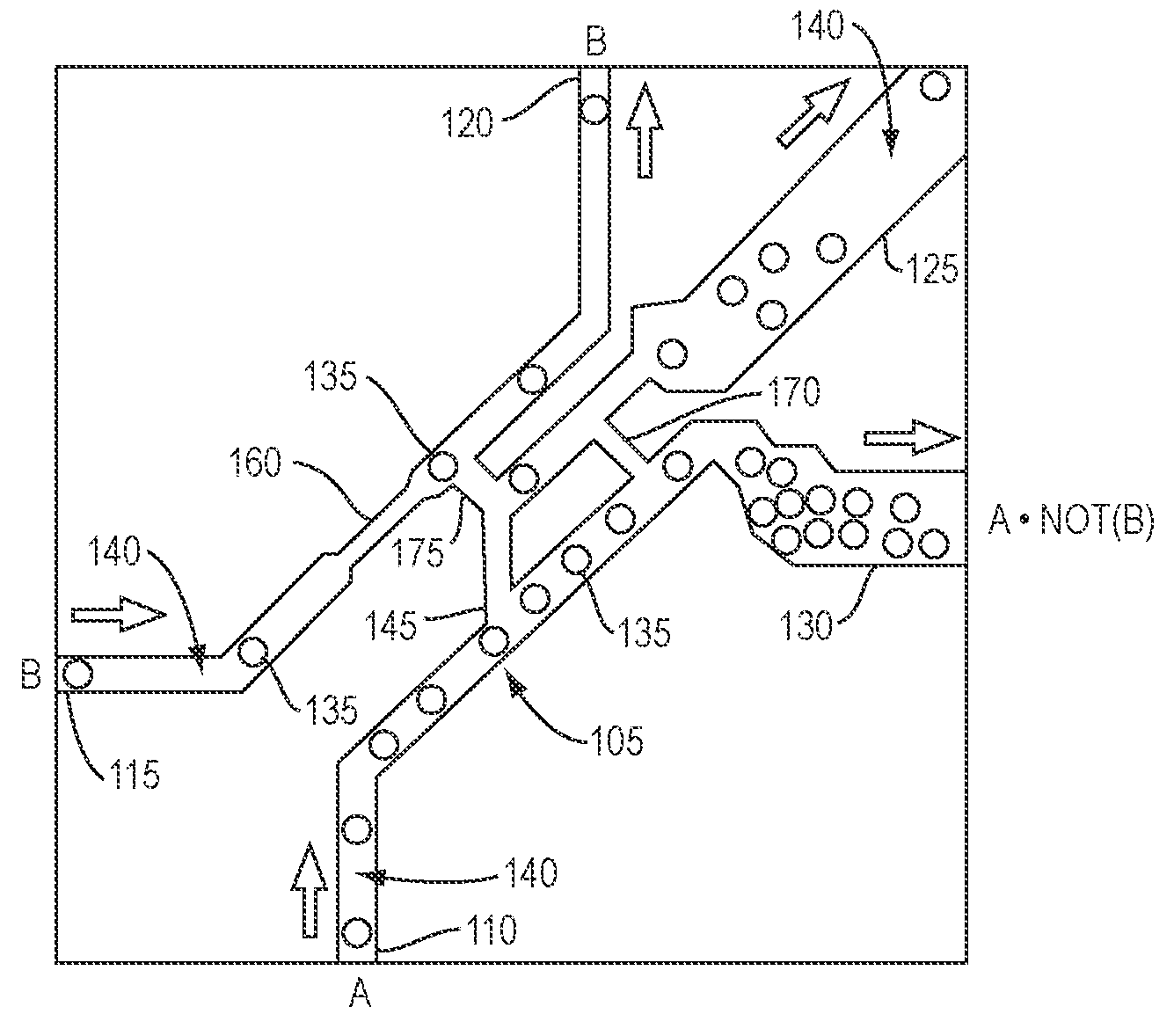
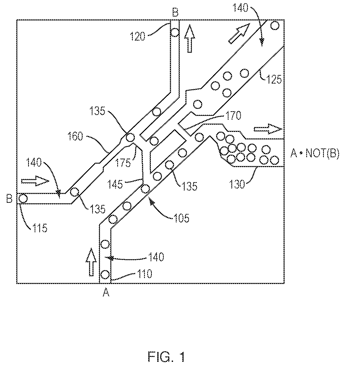
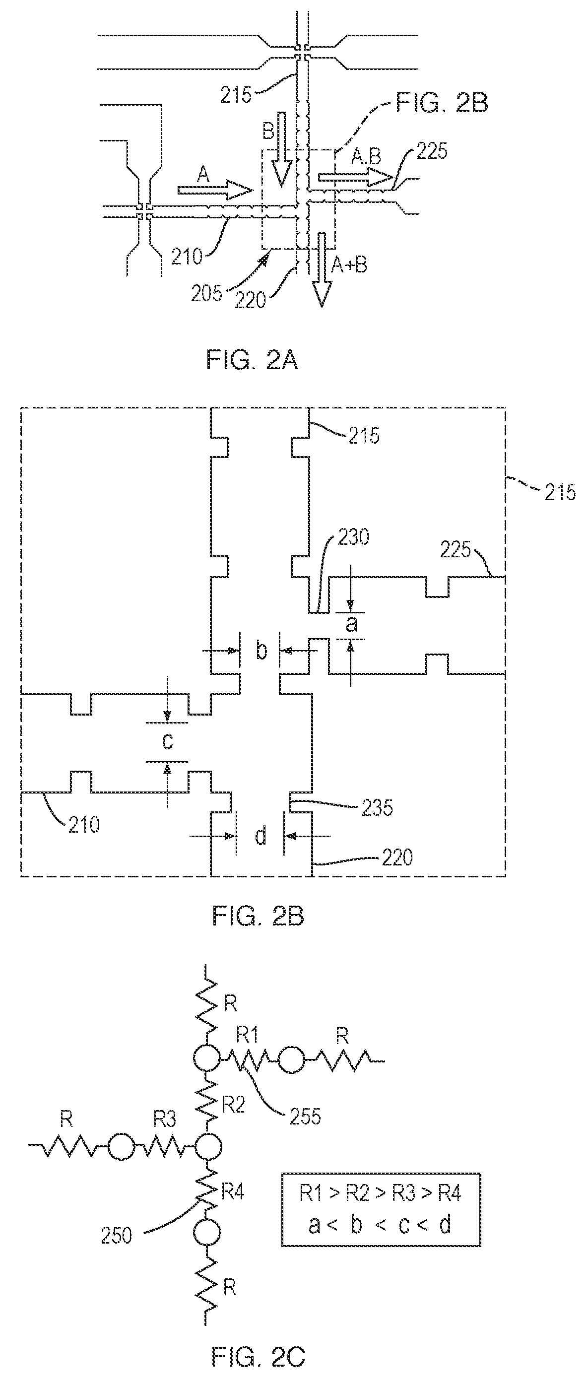
[0083]The present invention is an all fluid-based no-moving part micro-mechanical logic family. The fluidic logic of the present invention works for very low reynolds number, thus making it possible to build devices at micron-sized scales. This is the first time an all-fluidic, no moving-part logic family has been designed that employs newtonian fluids at small length scales. The working principle is based on minimum energy interfaces in two-phase newtonian fluid-dynamic systems. The input to the system is a sequence of air bubbles encoding information, with the output being another sequence of air bubbles.

[0084]The micro-mechanical logic family of the present invention includes logic devices, modulators, pressure sensors, actuators, and an all-fluidic means to control them based on two-phase fluid flow in micro-channels. Miniaturized microfluidic devices based on micron-sized channels and complex plumbing networks are extensively used as a research platform in several areas includi...


PUM


Abstract

Fluid-based no-moving part logic devices are constructed from complex sequences of micro- and nanofluidic channels, on-demand bubble / droplet modulators and generators for programming the devices, and micro- and nanofluidic droplet / bubble memory elements for storage and retrieval of biological or chemical elements. The input sequence of bubbles / droplets encodes information, with the output being another sequence of bubbles / droplets or on-chip chemical synthesis. For performing a set of reactions / tasks or process control, the modulators can be used to program the device by producing a precisely timed sequence of bubbles / droplets, resulting in a cascade of logic operations within the micro- or nanofluidic channel sequence, utilizing the generated droplets / bubbles as a control. The devices are based on the principle of minimum energy interfaces formed between the two fluid phases enclosed inside precise channel geometries. Various devices, including logic gates, non-volatile bistable memory, ring oscillators, bubble synchronizers, analysis chips, and printers have been designed.

Description

RELATED APPLICATIONS[0001]This application claims the benefit of U.S. Provisional Application Ser. No. 60 / 900,301, filed Feb. 8, 2007, the entire disclosure of which is herein incorporated by reference.[0002]This application is a continuation-in-part of U.S. patent application Ser. No. 11 / 416,449, filed May 2, 2006, the entire disclosure of which is herein incorporated by reference and which claims the benefit of U.S. Provisional Application Ser. No. 60 / 676,910, filed May 2, 2005, the entire disclosure of which is herein incorporated by reference.STATEMENT REGARDING FEDERALLY SPONSORED RESEARCH OR DEVELOPMENT[0003]This invention was made with U.S. government support under Grant Number NSF CCR-0122419, awarded by the National Science Foundation. The government has certain rights in this invention.FIELD OF THE TECHNOLOGY[0004]The present invention relates to micromechanical logic circuits and, in particular, to fluidic logic devices employing multi-phase Newtonian fluid dynamic system...

Claims


Application Information

Patent Timeline
Patent Type & Authority Patents(United States)
IPC IPC(8): F15B21/00
CPCF16K99/0001F16K99/0019F16L55/00G01N15/06G01N1/2035F16K2099/0084F16K2099/0092Y10T436/11G01N2001/002Y10T436/25625Y10T436/2575Y10T436/25Y10T137/9247Y10T137/87249Y10T137/2076Y10T137/87153B01L3/502746B01L3/502784B01L2200/0673B01L2300/02B01L2400/086
Inventor PRAKASH, MANUGERSHENFELD, NEIL
Owner MASSACHUSETTS INST OF TECH
Learn More