Eureka AIR delivers breakthrough ideas for toughest innovation challenges, trusted by R&D personnel around the world.

Method of fabricating micromechanical components with free-standing microstructures or membranes

a microstructure or membrane technology, applied in the field of manufacturing micromechanical components with freestanding microstructures or membranes, can solve the problems of mechanical stress in the polysilicon, low precipitation rate of the lpcvd reactor layer, and inconvenient precipitation process

Inactive Publication Date: 2011-04-05
FRAUNHOFER ZUR FOERDERUNGDER
View PDF15 Cites 7 Cited by
  • Summary
  • Abstract
  • Description
  • Claims
  • Application Information

AI Technical Summary

Benefits of technology

[0020]An oxide layer prevents the formation of monocrystalline silicon during precipitation of polysilicon on a silicon wafer. To improve the nucleation, a thin LPCVD polysilicon layer may initially be deposited on the oxide layer. Substrates of ceramics, quartz or other materials may also be used.
[0021]In an improvement of the method in accordance with the invention, the conductivity of the polysilicon layer is improved by admixing defined quantities of gases containing boron or phosphorus (e.g. phosphine (PH3)) to the reaction gas. Layer resistances (the layer resistance in Ω / □ is the result of integrating the conductance over the depth of the polysilicon layer) between 10Ω / □ to several kΩ / □ may be generated by such in situ doping. In this manner, the polysilicon material is rendered electrically conductive, and the evaluation of, or the activation by, electrical signals of sensors and actuators is made possible.
[0022]Additional layers with high internal tensile stresses may be deposited above and / or below the polysilicon layer to generate high prestresses, e.g. for improving the stiffness of the membranes.

Problems solved by technology

However, the LPCVD reactors have relatively low layer precipitation rates of about 20 nm / min.
Hence, for applications requiring layer thicknesses of up to several 10 μm, this precipitation process is not suitable.
A further disadvantage of polysilicon layers fabricated in these systems resides in the resulting mechanical stress in the polysilicon.
Different tests have shown, however, that the tension values generated in the polysilicon layer by the mentioned processes can only be poorly reproduced.
Moreover, the layer thickness which may be obtained within reasonable processing times is limited to about 2 μm, so that such processes are not suitable for free-standing structures requiring layer thicknesses up to several 10 μm.

Method used


Image

  • Method of fabricating micromechanical components with free-standing microstructures or membranes
  • Method of fabricating micromechanical components with free-standing microstructures or membranes
  • Method of fabricating micromechanical components with free-standing microstructures or membranes

Examples


Embodiment Construction

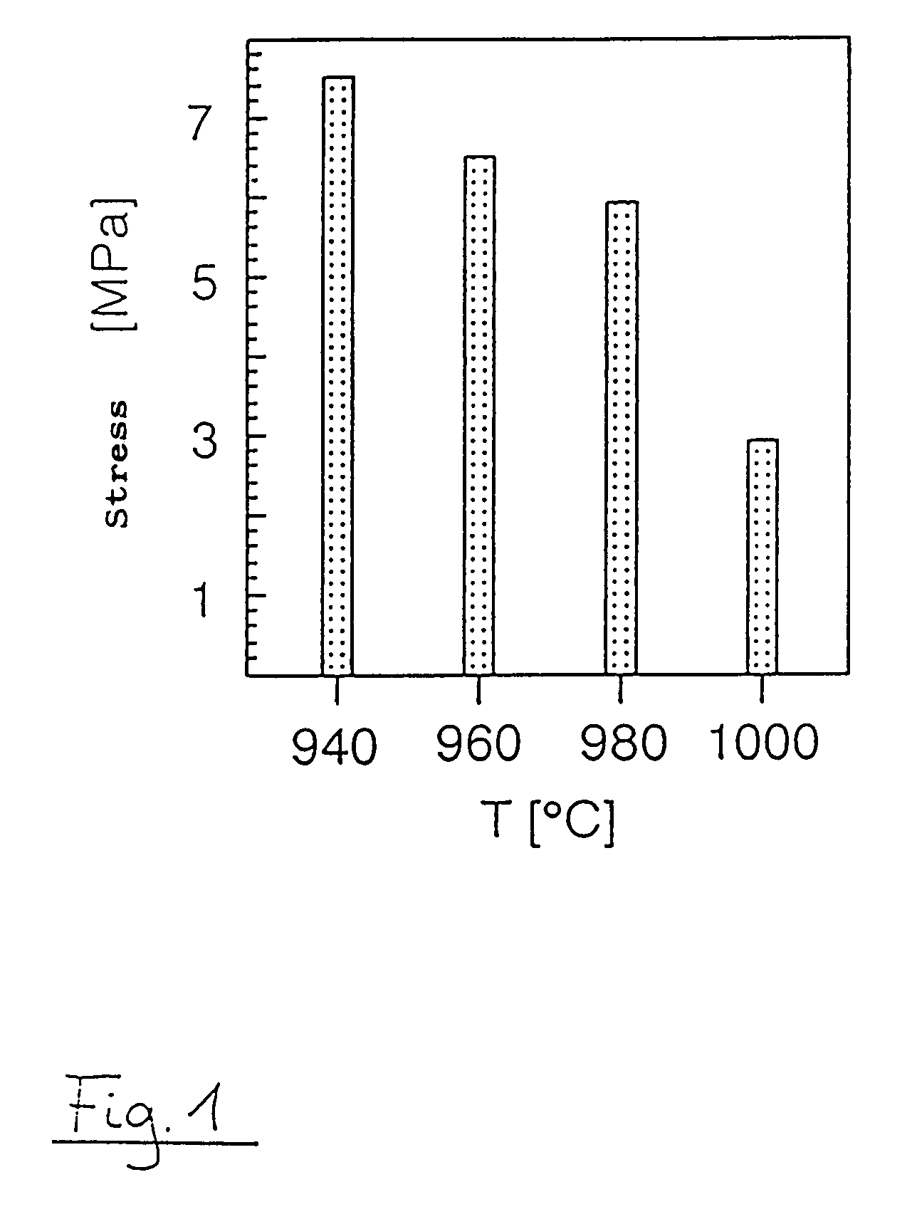
[0027]An example of different tensile stresses of polysilicon layers deposited by the method in accordance with the invention at vacuum pressure (here: 10.6×10³ Pa) is shown in FIG. 1. The dependence of the stress values on process temperature may be clearly seen. In a temperature range between 940° C. and 1,000° C. the tension varies between about 7.5 MPa and 3 MPa.

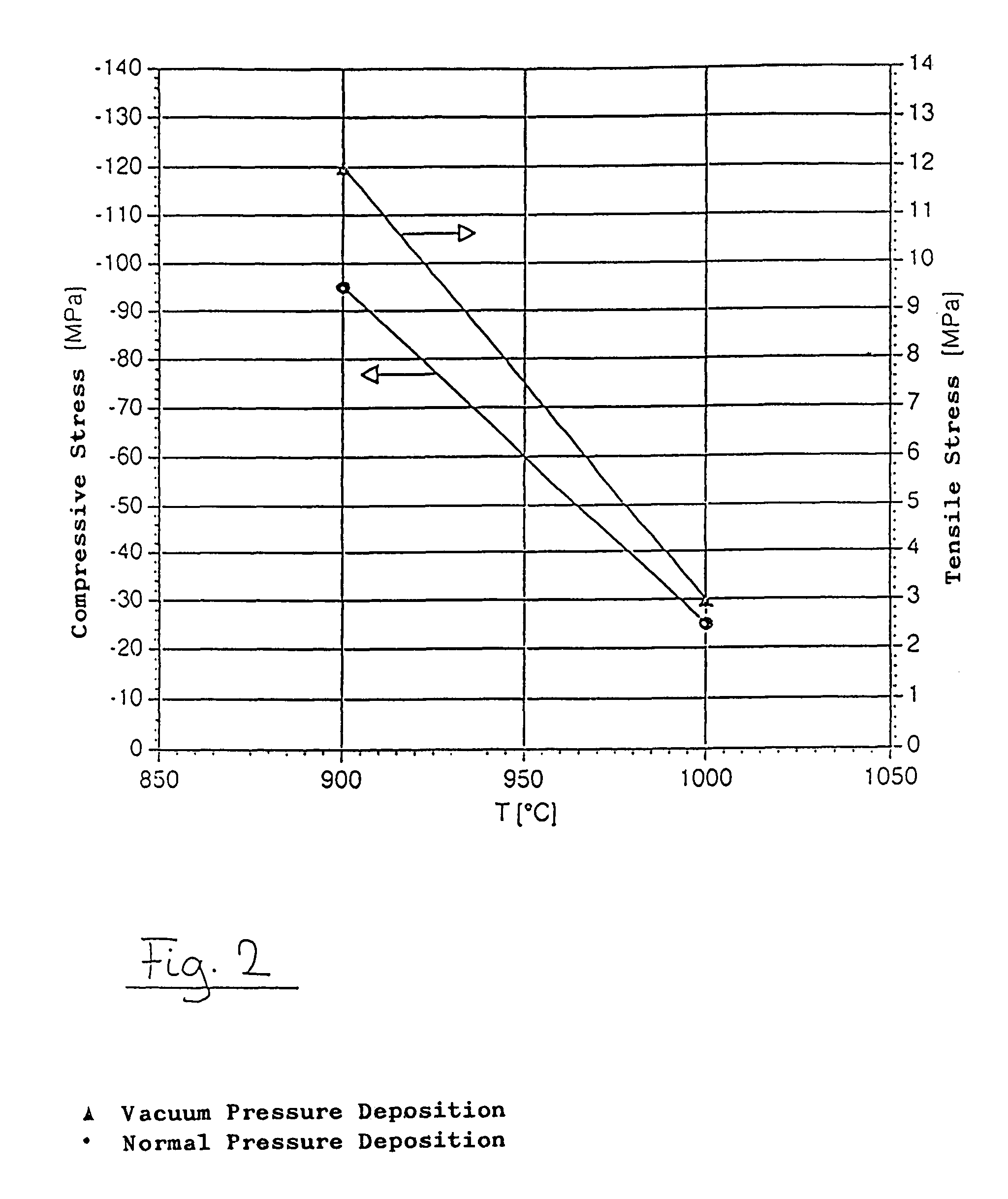
[0028]FIG. 2 depicts the dependence of internal stresses of polysilicon layers deposited in accordance with the invention on process temperature (shown in solid line) at two different process pressure settings. As the process temperatures are increased, the stress values of the polysilicon layers drop in respect of both compressive as well as tensile stresses. Low value tensile stresses are generated at vacuum pressure precipitation (10.6×10³ Pa; shown by solid triangles), as contrasted to compressive stresses up to 0.1 GPA at normal pressure (atmospheric pressure; depicted by filled circles).

[0029]An embodiment of fabri...


PUM

PropertyMeasurementUnit
Temperatureaaaaaaaaaa

Abstract

A method is disclosed of fabricating micromechanical components provided with free-standing microstructures or membranes with predetermined mechanical stress, by initially depositing a sacrificial layer on a substrate followed by depositing a polysilicon layer on the sacrificial layer by a gaseous phase deposition and, finally, at least partial removal of the sacrificial layer. During deposition of the polysilicon layer, the process pressure selected determined the type of stress in the polysilicon layer, and the value of the stress is set by the process temperature selected. The process pressure is above the pressure range used in LPCVD reactors.

Description

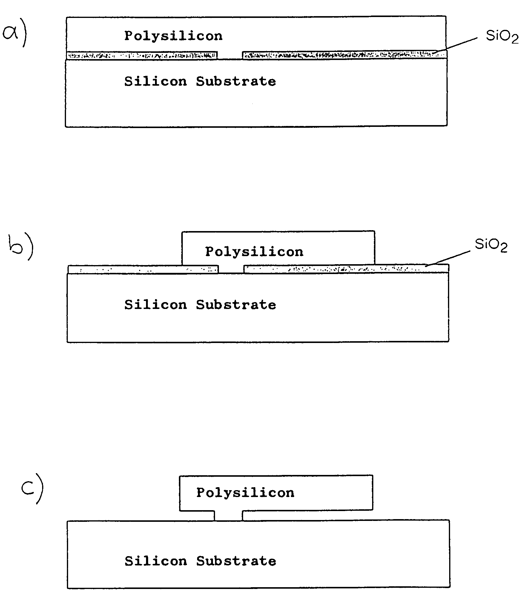
BACKGROUND OF THE INVENTION[0001]1. Field of the Invention[0002]The invention relates to a method of fabricating micromechanical components with free-standing microstructures or membranes under predeterminable mechanical stresses.[0003]2. The Prior Art[0004]Aside from bulk micromachining in which three-dimensional structures are etched out of a wafer by anisotropic selective etching solutions, so-called surface micromachining has gained ever increasing significance. With this technology, free-standing moveable microstructures may be fabricated on a substrate surface. Sandwich systems of distinct layers which may be etched with respect of each other form the basis for these structures. After structuring of the uppermost layer (e.g. of polysilicon) the sacrificial layer positioned beneath it (e.g. silicon dioxide) is removed by a wet chemical process, so that free-standing structures are formed which may be shaped like bridges or tongues.[0005]The material chiefly used for these mecha...

Claims


Application Information

Patent Timeline
IPC IPC(8): H01L21/00B81C1/00C23C16/24C23C16/52H01L21/205
CPCC23C16/24C23C16/52H01L21/02488H01L21/02381H01L21/0262H01L21/02422H01L21/02532H01L21/02587H01L21/0242
Inventor KIRSTEN, MARIOLANGE, PETERWENK, BEATRICERIETHMUELLER, WERNER
Owner FRAUNHOFER ZUR FOERDERUNGDER
Why Eureka
Eureka Blog
Learn More