

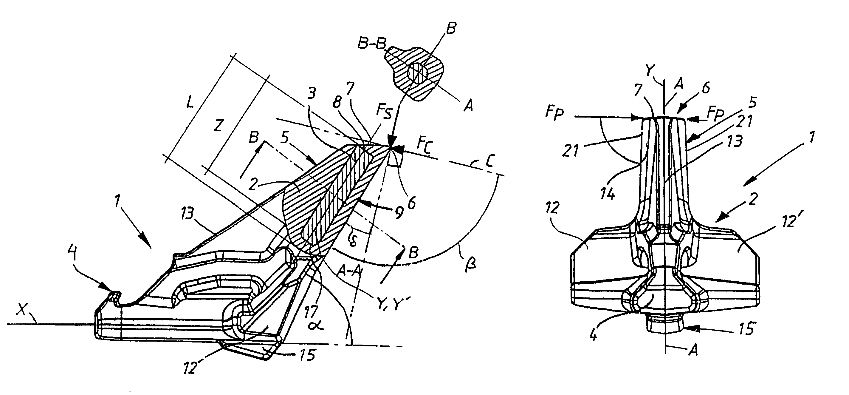
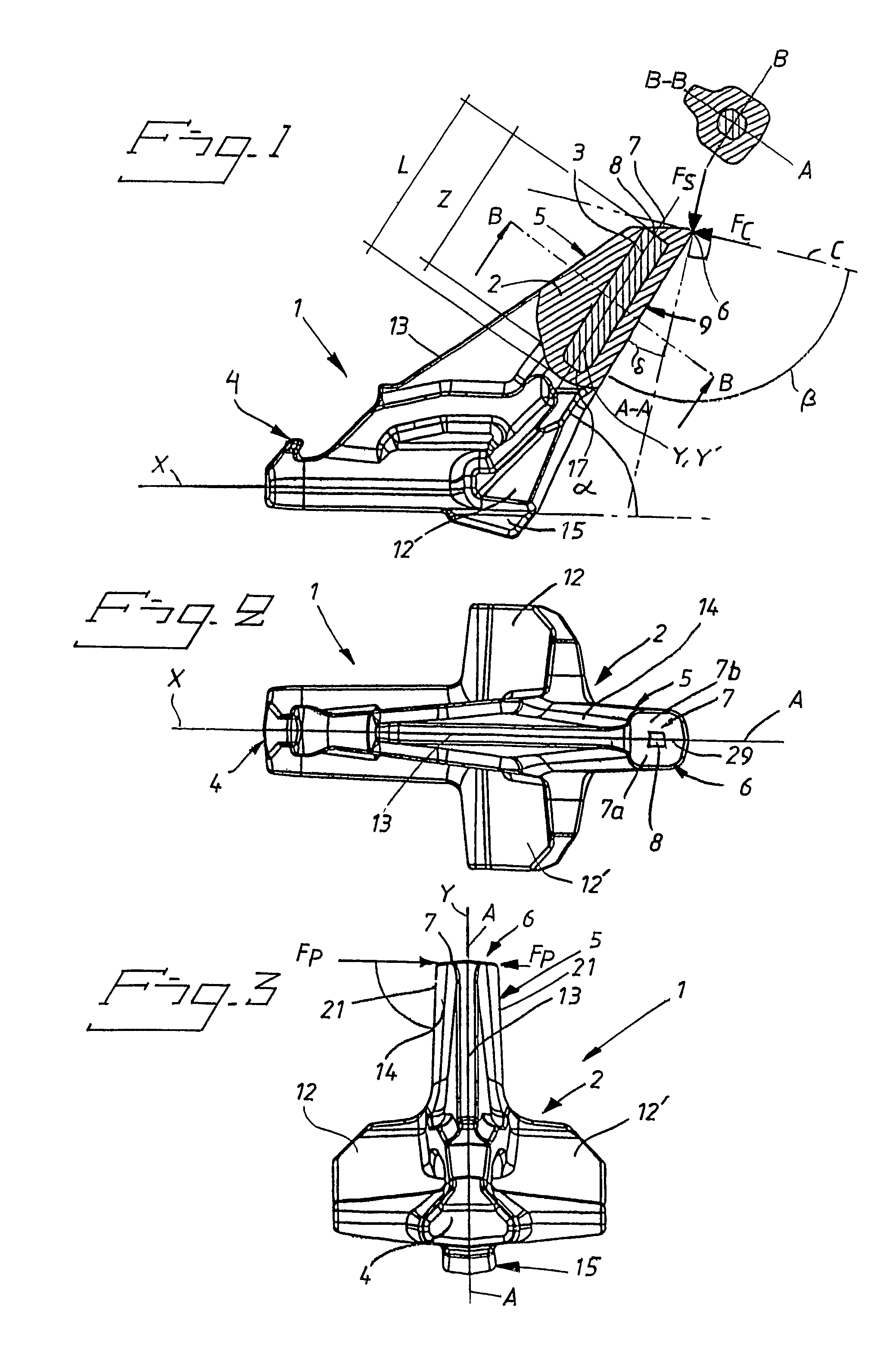
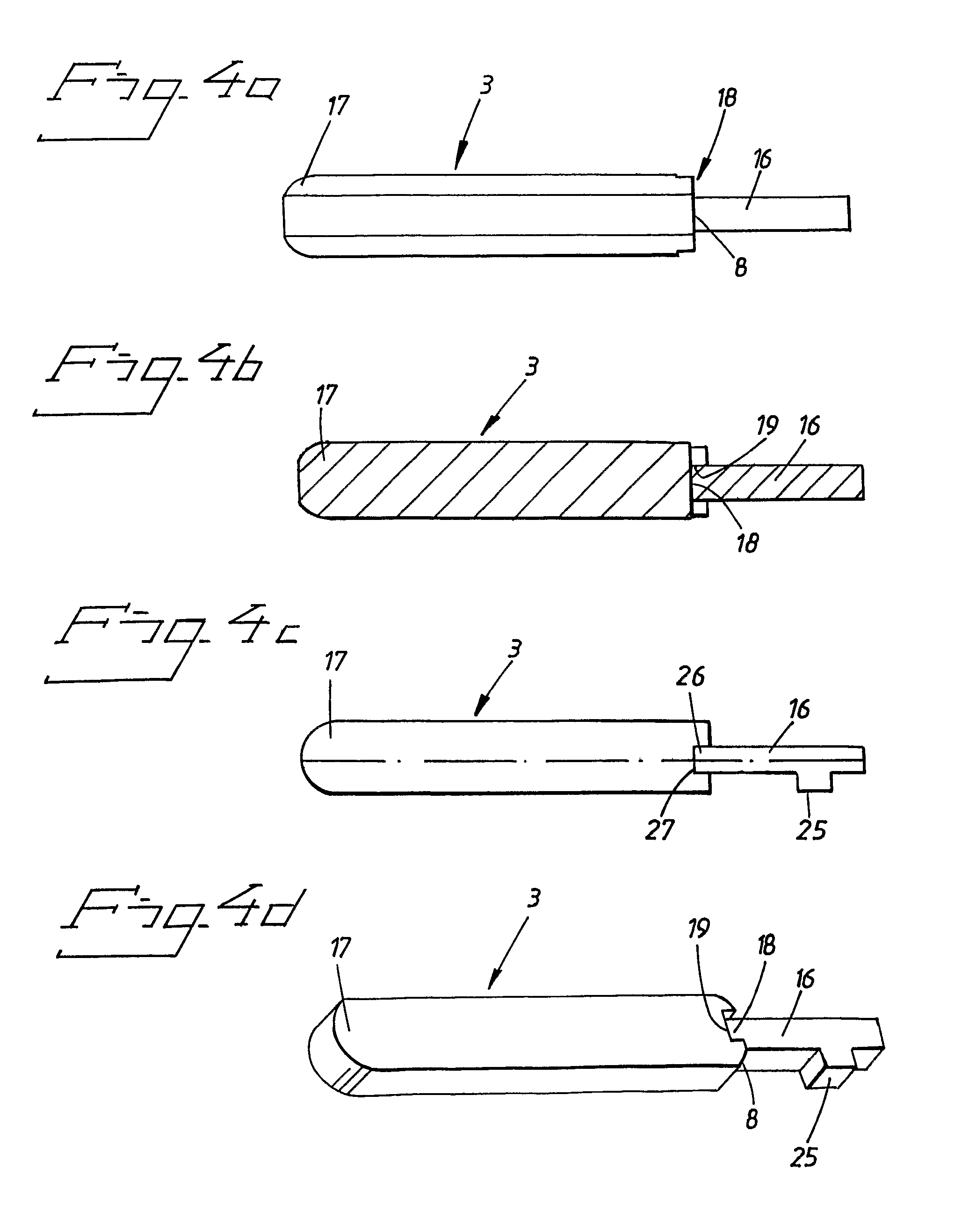
Self-sharpening, auto-signalling wearing part
a technology of wearing parts and auto-signaling, which is applied in the field of wearable parts, can solve the problems of tooth neck wear, wear and tear of bearing surfaces or other working surfaces, and wear and tear of teeth, and achieve the effects of improving hardness against wear, improving performance, and low carbon conten
- Summary
- Abstract
- Description
- Claims
- Application Information
AI Technical Summary
Benefits of technology
Problems solved by technology
Method used
Image

Examples
embodiment 1
Illustrative Embodiment 1
Percent by Weight
The Chemical Composition of the Cast Steel:
[0101]C 0.24-0.28% by weight[0102]Si 1.40-1.70% by weight[0103]Mn 1.00-1.40% by weight[0104]P max 0.025% by weight, preferably 0.020% by weight[0105]S max 0.020% by weight, preferably 0.013% by weight[0106]Cr 1.25-1.50% by weight[0107]Ni 0.40-0.60% by weight[0108]Mo 0.17-0.22% by weight[0109]Al max 0.03-0.08% by weight, preferably 0.045% by weight[0110]Ti max 0.04-0.10% by weight, preferably 0.07% by weight[0111]N max 180 ppm, preferably 120 ppm,[0112]DI hardenability index min 6.6, preferably 7.3, max 10.8.
Heat Treatment:
[0113]Full annealing / normalization at 900-1050° C. Time: min 3 hours±1 hour, or 1 hour / 25 mm length.
[0114]Cooling in the open air, heating to 850-1000° C. Time: 1 hour±0.5 hour. Hardening in water-polymer bath or water.
[0115]Tempering at 200-300° C. Time: 3 hours±1 hour, or 1 hour per 25 mm length, cooling in the open air. All times are based on the whole of the component part bein...
embodiment 2
Illustrative Embodiment 2
Percent by Weight
The Chemical Composition of the Cast Steel:
[0120]C 0.31-0.36% by weight[0121]Si 1.10-1.50% by weight[0122]Mn 0.80-1.10% by weight[0123]P max 0.025% by weight, preferably 0.015% by weight[0124]S max 0.015% by weight, preferably 0.010% by weight[0125]Cr 1.00-1.40% by weight[0126]Ni max 0.50% by weight[0127]Mo 0.20-0.30% by weight[0128]Al max 0.03-0.08% by weight, preferably 0.045% by weight[0129]Ti max 0.04-0.10% by weight, preferably 0.07% by weight[0130]N max 180 ppm, preferably 120 ppm,[0131]DI hardenability index min 6.6, preferably 7.3, max 10.8.
Heat Treatment:
[0132]Full annealing / normalization at 900-1050° C. Time: min 3 hours±1 hour, or 1 hour / 25 mm length.
[0133]Cooling in the open air, heating to 850-1000° C. Time: 1 hour±0.5 hour. Hardening in water-polymer bath or water.
[0134]Tempering at 200-300° C. Time: 3 hours±1 hour, or 1 hour per 25 mm length, cooling in the open air. All times are based on the whole of the component part being...
example 1
[0140]Cylindrical hard-metal rods of 22 mm diameter and 120 mm length, with 5% by weight Ni and 10% by weight Co, and the rest tungsten carbide (WC) of 4 μm grain size, were produced by conventional powder metallurgical methods. The carbon content was 5.2% by weight and the hardness 1140 HV3.
[0141]The rods were fixed in moulds for producing wearing teeth for the VOSTA T4 system, which is used in the cutter head for a dredger. A CNM85-type steel, with 0.26% by weight C, 1.5% by weight Si, 1.2% by weight Mn, 1.4% by weight Cr, 0.5% by weight Ni and 0.2% by weight Mo, Ceq=0.78, was melted down, and the molten mass with temperature of 1570° C. was poured into the moulds. The hard metal rod was preheated by the cast steel melt passing into the mould around the hard metal rod fixed there in correct position. Following air cooling, the teeth were normalized at 950° C. and hardened at 920° C. Tempering at 250° C. was the final stage in the heat treatment before the product acquired its fina...
PUM
| Property | Measurement | Unit |
|---|---|---|
| angle | aaaaa | aaaaa |
| width | aaaaa | aaaaa |
| width | aaaaa | aaaaa |
Abstract
Description
Claims
Application Information