Magnetic recording medium, method of manufacturing the same, and magnetic recording/reproducing apparatus

a technology of magnetic recording medium and manufacturing method, which is applied in the direction of magnetic bodies, instruments, record information storage, etc., can solve the problems of weakened magnetic field applied from the head, large thickness of the medium layer, and high degree of crystal orientation. , to achieve the effect of small thickness range, uniform diameter and high degree of crystal orientation

Inactive Publication Date: 2011-10-11
RESONAC HOLDINGS CORPORATION +2
View PDF10 Cites 0 Cited by
  • Summary
  • Abstract
  • Description
  • Claims
  • Application Information

AI Technical Summary

Benefits of technology

[0036]According to the present invention, since the seed layer has a predetermined crystal structure, the seed layer has fine crystal particles with a uniform diameter and a high degree of crystal orientation in a relatively small thickness range. Therefore, the intermediate layer and the magnetic recording layer provided on the seed layer also include fine crystal particles with a uniform diameter and a high degree of crystal orientation, according to the diameter and orientation of the crystal particles in the seed layer. For example, in the magnetic recording layer having the hexagonal close-packed (hcp) structure, a crystal c-axis is aligned with the surface of the non-magnetic substrate with a small angular variance.
[0037]Since the magnetic recording layer includes fine crystal particles with a uniform diameter, the recording bit transition boundary line becomes a smooth straight line, and good characteristics can be obtained in a high recording density region.
[0038]Since the seed layer has a high degree of crystal orientation in a relatively small thickness range, it is possible to ensure sufficient crystal orientation and reduce the thickness thereof. In this way, it is possible to reduce the distance between the soft magnetic underlayer and the magnetic recording layer. In addition, when the recording head applies a recording magnetic field, it is possible to reduce the distance between the recording head and the soft magnetic underlayer. As a result, the magnetic field from the recording head is effectively applied to the magnetic recording layer, and it is possible to obtain a high level of writing performance.

Problems solved by technology

However, the perpendicular magnetic recording medium has an advantage in that it can use a relatively thick magnetic recording layer, but it has disadvantages in that the total thickness of the layers of the medium is likely to be larger than in the longitudinal magnetic recording medium and the crystal structure is likely to be disordered during a process of forming thin films of a medium.
As a result, during recording, the magnetic field applied from the head is weakened, and the writing performance is reduced.
When the seed layer having the face-centered cubic (fcc) structure is used, it is difficult to improve the crystal orientation and obtain fine particles with a uniform diameter.
As described above, the seed layer made of a crystal material having the face-centered cubic (fcc) structure or the hexagonal close-packed (hcp) structure is insufficient to obtain a perpendicular magnetic recording medium having good read / write characteristics.

Method used


Image

  • Magnetic recording medium, method of manufacturing the same, and magnetic recording/reproducing apparatus
  • Magnetic recording medium, method of manufacturing the same, and magnetic recording/reproducing apparatus
  • Magnetic recording medium, method of manufacturing the same, and magnetic recording/reproducing apparatus

Examples


example 1-1

[0114]First, an HD glass substrate was set in a vacuum chamber of a sputtering apparatus, and the vacuum chamber was evacuated to a pressure of 1.0×10⁻⁵ Pa or less.

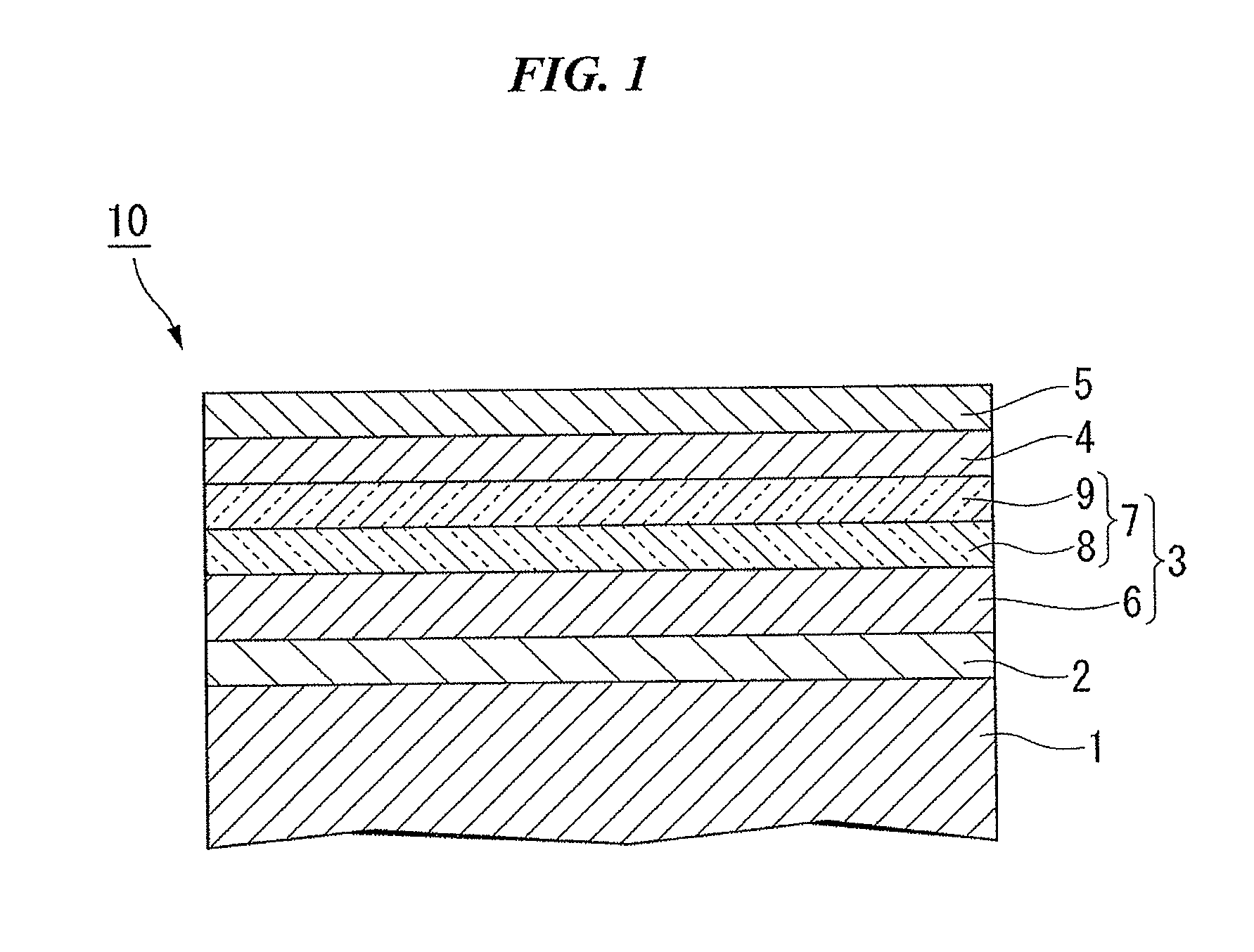
[0115]Then, a soft magnetic underlayer (thickness: 50 nm) made of Co-10Ta-5Zr was formed on the glass substrate in an Ar atmosphere by a sputtering method. In this case, the pressure of Ar gas was 0.6 Pa. (In the composition formula of each alloy, a number given to the front side of each element indicates the content (at %) of each element in the alloy, and the content of an element given no number is the remaining content of the other element).

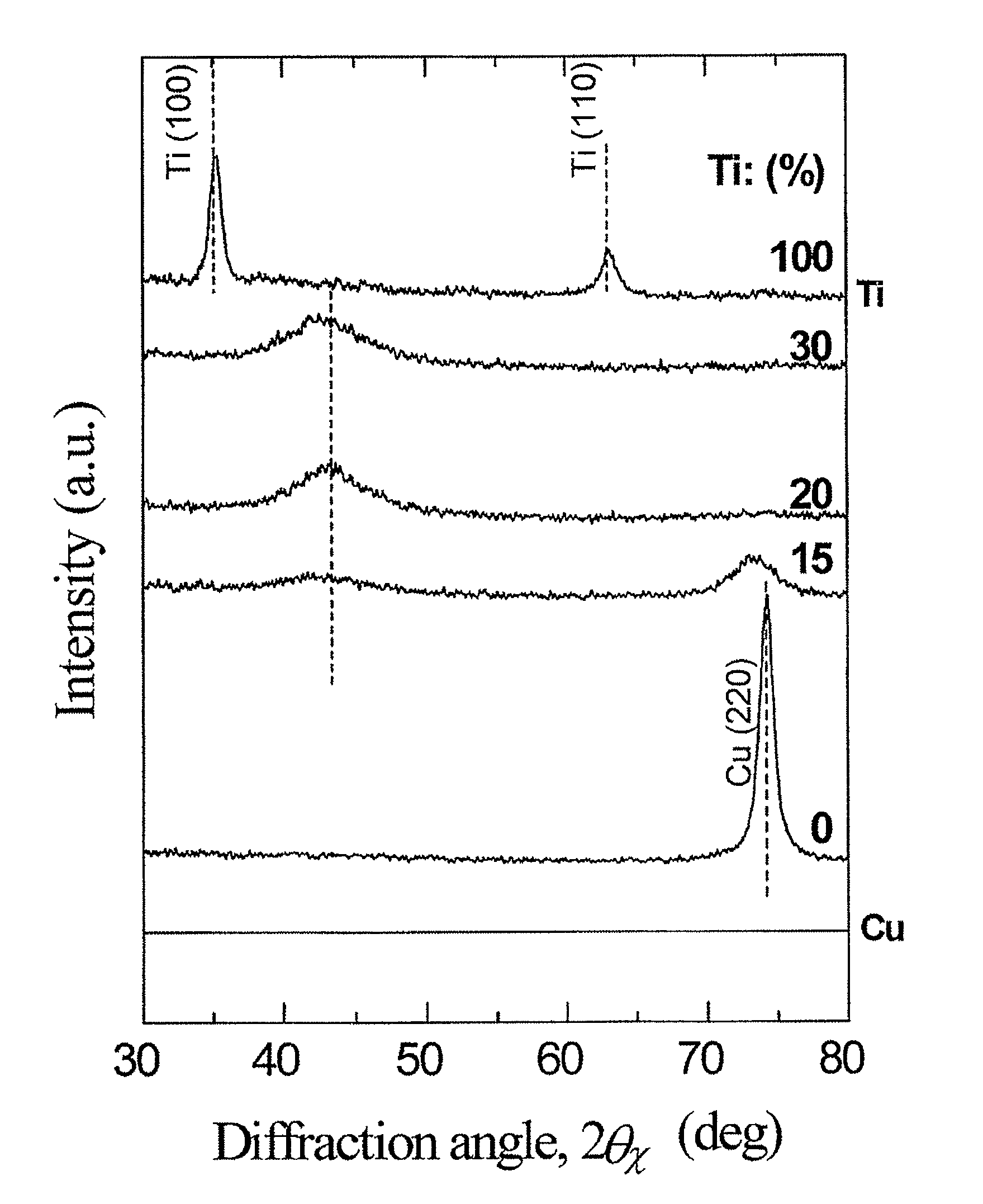
[0116]Then, a seed layer (thickness: about 5 nm) made of Cu-7Ti was formed on the soft magnetic underlayer in an Ar atmosphere by the sputtering method. In this case, the pressure of Ar gas was 0.6 Pa.

[0117]The profile of the seed layer was observed by In-plane X-ray diffraction. As a result, a peak caused by the fcc (220) crystal plane and another peak on the low-angle side of the...

examples 1-2 and 1-3

[0122]A perpendicular magnetic recording medium was manufactured by the same method as that in Example 1-1 except that the composition of the seed layer was changed as shown in Table 1.

[0123]The profile of the seed layer formed in each magnetic recording medium was observed by In-plane X-ray diffraction. As a result, a peak caused by the fcc (220) crystal plane and another peak arranged on the low-angle side of the peak were observed. The observation result proved that each seed layer had the pseudo-hexagonal structure in which the fcc (111) crystal plane was oriented substantially perpendicular to the surface of the substrate.

example 2-1

[0136]Similar to Example 1-1, a soft magnetic underlayer was formed on a glass substrate.

[0137]Then, a seed layer (thickness: about 4 nm) made of Cu-7Ti was formed on the soft magnetic underlayer in an Ar atmosphere by the sputtering method. In this case, the pressure of Ar gas was 0.6 Pa.

[0138]Then, a first intermediate layer (thickness: 8 nm) made of Ru was formed on the seed layer in an Ar atmosphere by the sputtering method. In this case, the pressure of Ar gas was 0.6 Pa.

[0139]Then, a second intermediate layer (thickness: 8 nm) made of Ru was formed on the first intermediate layer in an Ar atmosphere by the sputtering method. In this case, the pressure of Ar gas was 10 Pa.

[0140]Then, a magnetic recording layer (thickness: 12 nm) made of 90(Co-12Cr-20Pt)-10(SiO2) (a number given to the front side of the composition formula of each composite indicates the content (mol %) of each composite) was formed on the second intermediate layer in an Ar atmosphere by the sputtering method. I...


PUM

PropertyMeasurementUnit
thicknessaaaaaaaaaa
thicknessaaaaaaaaaa
particle diameteraaaaaaaaaa

Abstract

The present invention provides a magnetic recording medium which is capable of improving the perpendicular orientation of a perpendicular magnetic recording layer while maintaining a writing performance during recording and obtaining both an improvement in the perpendicular orientation and fine magnetic crystal particles with a uniform diameter, and which enables information to be recorded or reproduced at high density, a method of manufacturing the same, and a magnetic recording / reproducing apparatus. A magnetic recording medium 10 according to the present invention includes at least a soft magnetic underlayer 2, an orientation control layer 3, a magnetic recording layer 4, and a protective layer 5 formed on a non-magnetic substrate 1. The orientation control layer 3 has a seed layer 6 and an intermediate layer 7. The seed layer 6 is made of a Cu—Ti alloy that has a face-centered cubic structure and includes Cu as a main component. The Cu—Ti alloy has a (111) crystal plane oriented substantially perpendicular to the surface of the non-magnetic substrate 1 and has a pseudo-hexagonal structure.

Description

BACKGROUND OF THE INVENTION[0001]1. Field of the Invention[0002]The present invention relates to a magnetic recording medium, a method of manufacturing the same, and a magnetic recording / reproducing apparatus using the magnetic recording medium.[0003]Priority is claimed on Japanese Patent Application No. 2008-209907, filed Aug. 18, 2008, the content of which is incorporated herein by reference.[0004]2. Description of Related Art[0005]In recent years, the application range of magnetic recording apparatuses, such as magnetic disk apparatuses, flexible disk apparatuses, and magnetic tape apparatuses, has increased remarkably, and their importance thereof has increased. Therefore, a technique has been developed for significantly improving the recording density of magnetic recording media used for these apparatuses. In particular, the development of an MR (magneto resistive) head and a PRML (partial response maximum likelihood) technique has accelerated the improvement in the areal recor...

Claims


Application Information

Patent Timeline
Patent Type & Authority Patents(United States)
IPC IPC(8): G11B5/66
CPCB82Y25/00B82Y40/00G11B5/667G11B5/732H01F10/3272H01F41/306G11B5/65G11B5/7379G11B5/658
Inventor ISHIBASHI, SHINICHITAKAHASHI, MIGAKUSAITO, SHINSASAKI, YUZOHASHIMOTO, ATSUSHIKUROKAWA, GOHEIMAEDA, TOMOYUKITAKEO, AKIHIKO
Owner RESONAC HOLDINGS CORPORATION
Why Eureka
Try Eureka