Nanocarbon-reinforced polymer composite and method of making

a technology of reinforced polymer and composite material, which is applied in the direction of carbon-silicon compound conductors, non-metal conductors, conductors, etc., can solve the problems of undesirable effect, significant difficulty in incorporating vapor grown carbon fibers into a polymer matrix, and destroying the interconnections between fibers that are necessary, etc., to achieve complementary geometric and desired physical properties, low electrical resistance, and high surface area

Inactive Publication Date: 2011-11-01
APPLIED SCI
View PDF8 Cites 7 Cited by
  • Summary
  • Abstract
  • Description
  • Claims
  • Application Information

AI Technical Summary

Benefits of technology

[0008]The present invention meets that need by providing a method of making a polymer-based composite material which exhibits relatively low electrical resistivity in which graphitic carbon nanofibers are blended with nano-scale carbon additives or conductive metallic nano-scale materials having high surface area with complementary geometric and desired physical properties. Such nano-scale additives include carbon black, exfoliated carbon nanofibers, exfoliated graphite, and nano-graphene platelets, as well as non-conductive nano-clays or conductive nano-scale silver, aluminum, and other conductive metals. The resulting composite exhibits improved properties including higher transverse strength and stiffness, greater interlaminar shear strength and micro-cracking resistance, improved performance temperature, dimensional stability, and improved electrical and thermal conductivities.

Problems solved by technology

However, there is a significant difficulty when vapor grown carbon fibers are incorporated in a polymer matrix.
The high shearing forces of the equipment, which are designed to promote dispersion of the fibers, have a counter effect on the fiber length and network formation, destroying the interconnections between the fibers that are necessary for thermal and electrical conductivity in the composite.
Such an undesirable effect is particularly evident with the use of small diameter vapor grown carbon fibers, whose high surface area and stiffness can render the fibers too fragile for many types of production mixers.
While higher carbon fiber contents of 5 volume percent or higher can help reduce resistivity, such composites are more difficult to process and can exhibit unacceptable mechanical properties.

Method used


Image

  • Nanocarbon-reinforced polymer composite and method of making
  • Nanocarbon-reinforced polymer composite and method of making

Examples


Embodiment Construction

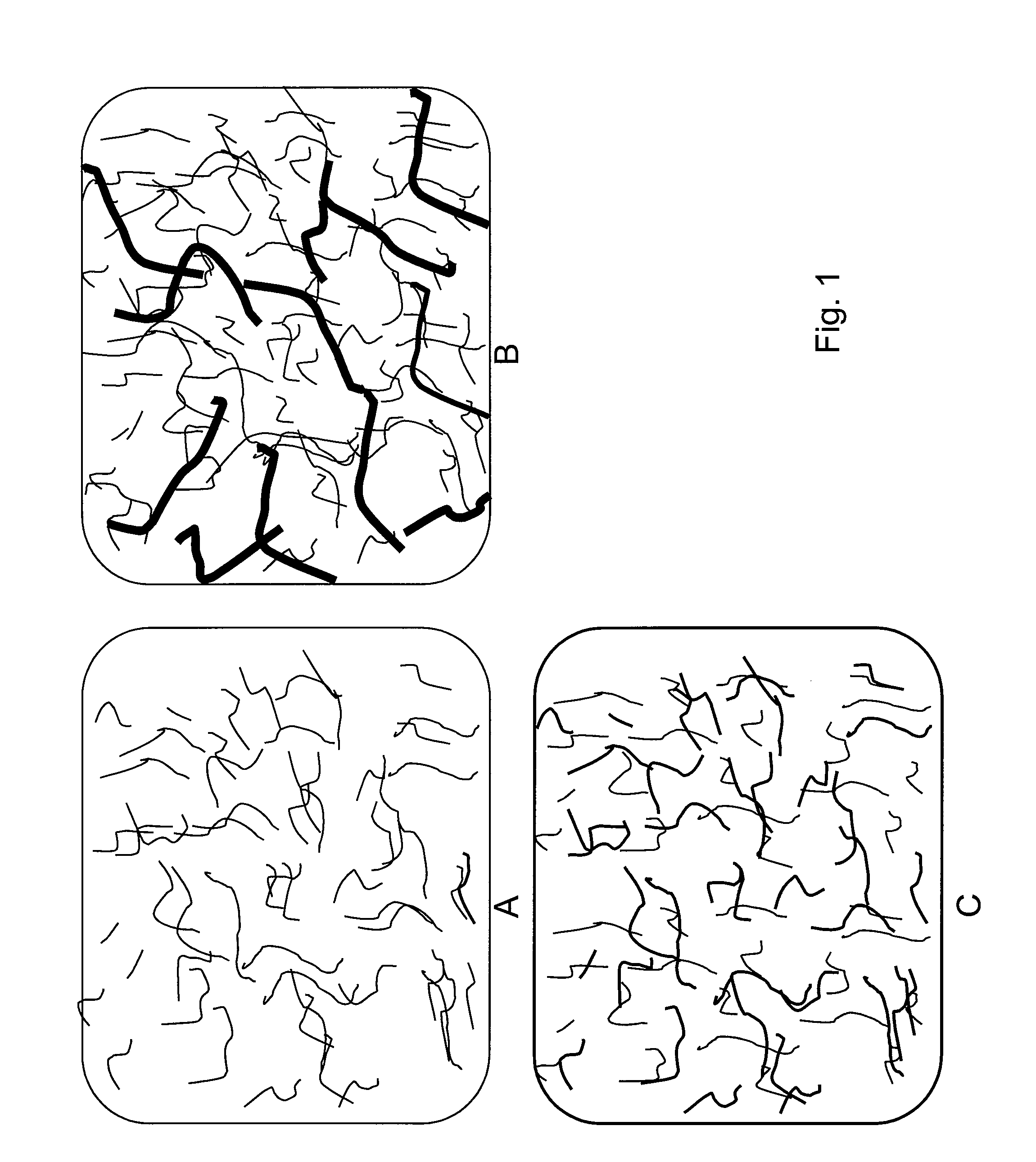
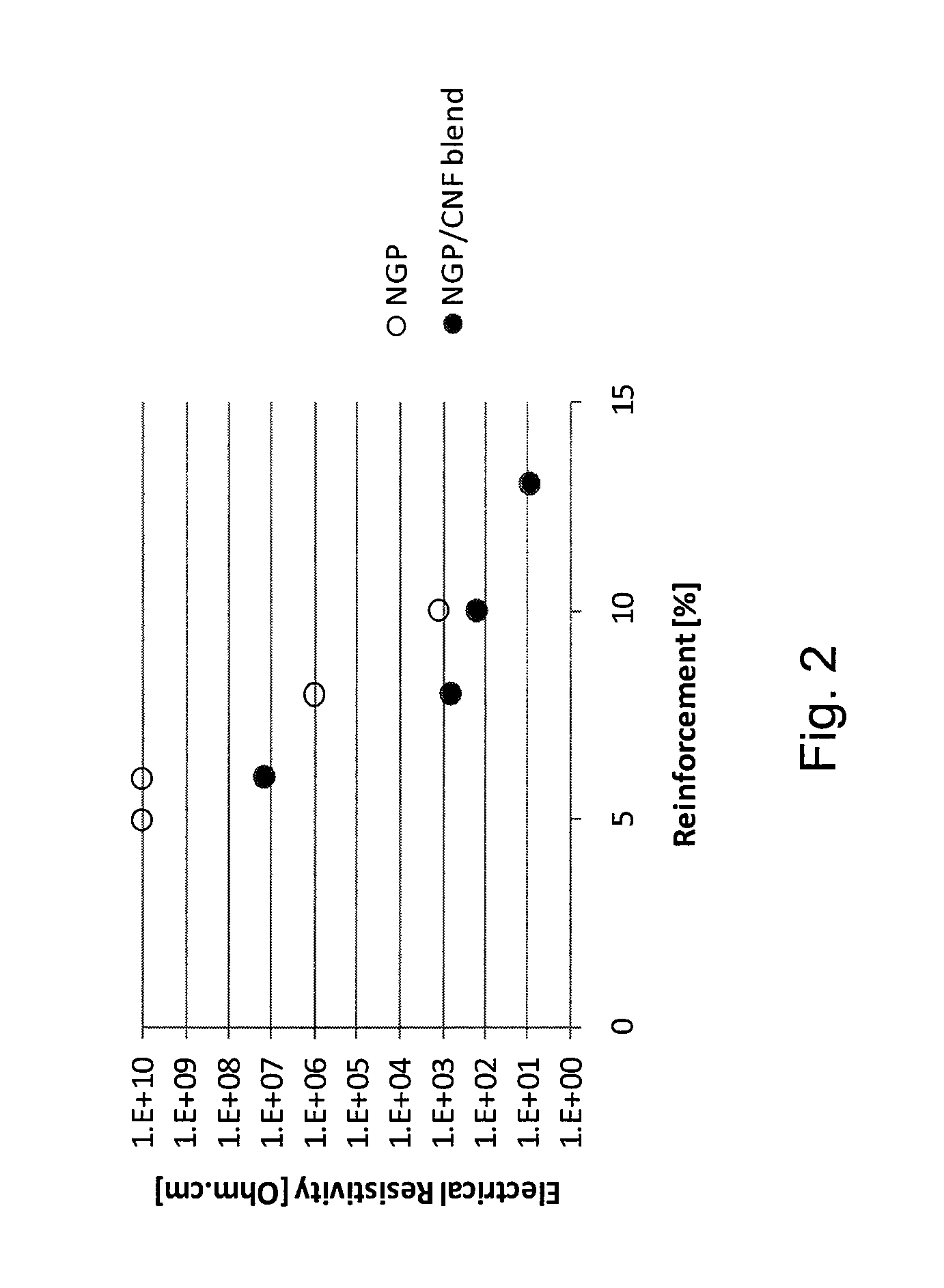
[0014]We have found that the combination of carbon nanofibers with other nano-scale particles provides an economical hybrid system having many synergistic properties. For example, carbon nanofibers have a large aspect ratio while nano-graphene platelets, for example, disperse easily and are low in cost. In addition, we have found that the combination of carbon nanofibers and nano-scale particles unexpectedly provides a lower overall electrical resistivity, and a lower percolation threshold for the onset of electrical conductivity than the use of either of these materials alone at equal loadings.

[0015]The resulting polymer composite preferably has an electrical resistivity of less than about 107 ohm-cm in the direction of the melt flow, or less than about 106 ohm-cm, or less than about 105 ohm-cm, or less than about 104 ohm-cm, or less than about 103 ohm-cm. The resistivity needed will depend on the application the material is being used in. For example, the resistivity should be in ...


PUM

PropertyMeasurementUnit
diameteraaaaaaaaaa
lengthaaaaaaaaaa
lengthaaaaaaaaaa

Abstract

A method of making a polymer composite from a mixture of a polymeric material, carbon nanofibers, and nano-scale particles is provided. The carbon nanofibers are less than about 1 micrometer in diameter, and the nano-scale particles are shorter in length than the carbon nanofibers. The nano-scale particles are selected from nano-scale carbon additives, non-conductive nano-clays, nano-scale conductive metallic additives, or combinations thereof. The components are mixed to form a polymer composite. A polymer composite having a resistivity of less than about 107 ohm-cm is also described.

Description

BACKGROUND OF THE INVENTION[0001]The present invention relates to a method of making a polymer-based composite material having improved mechanical and electrical properties, and more particularly, to a polymer composite which is reinforced with a blend of carbon nanofibers and nano-scale particles.[0002]Many applications exist where there is a need for the enhancement of conductivity in polymer materials: for example, in static electricity dissipation, automotive applications such as electrostatic painting of panels, and electromagnetic interference (EMI) shielding applications. Typically, polymers may be reinforced with additives including talc, carbon black, milled carbon fibers, or metallic particles to improve modulus of elasticity, or electrical conductivity, or a combination of these and other physical properties. The incorporation of such additives typically has a dramatic influence on the viscosity of the polymer, and, as a consequence, on the processing characteristics of t...

Claims


Application Information

Patent Timeline
Patent Type & Authority Patents(United States)
IPC IPC(8): H01B1/24
CPCB82Y30/00C08J5/005H01B1/24Y10S977/932
Inventor BURTON, DAVIDLAKE, PATRICKCASTRO, CARLA LEER R.
Owner APPLIED SCI
Why Eureka
Try Eureka