
Mass spectrometry unit

a mass spectrometry and unit technology, applied in the field can solve the problems of filament or ion detector failure, filament breaking, and inability to obtain correct measurement, so as to save power of mass spectrometry units, prevent a functional decrease, and efficiently use the mass spectrometry units

Active Publication Date: 2012-03-20
ULVAC INC
View PDF43 Cites 3 Cited by
  • Summary
  • Abstract
  • Description
  • Claims
  • Application Information

AI Technical Summary

Benefits of technology

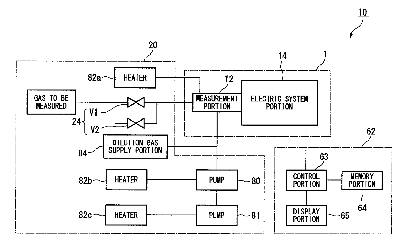
The present invention provides a mass spectrometry unit that can prevent a functional decrease in a specific portion and correctly grasp the deterioration time of the specific portion. The unit includes a control portion that preliminarily stores a record of mass-to-charge ratios of specific gases that decrease the function of the specific portion. If an ion current value with the mass-to-charge ratio of any of the specific gases detected by the mass spectrometry portion is not greater than a predetermined value, the control portion outputs a warning signal denoting a functional decrease in the specific portion and cancels an application of voltage to the specific portion to stop its function. The mass spectrometry unit also includes a specific portion maintenance device for preventing a functional decrease in the specific portion due to any of the specific gases. The invention aims to provide a mass spectrometry unit that can efficiently perform repair work and prevent unnecessary replacement of specific parts.

Problems solved by technology

However, faulty observance of instructions and directions for use of mass analyzers leads to a failure in a filament or an ion detector.
If the operating life is exceeded, it is not possible to obtain correct measurement.
At pressures more than that, there is a possibility that the filament will be broken.
In this case, a failure in the pumping system may lead to a failure in the mass analyzer.
When a mass spectrometry unit is used in such apparatuses, a corrosive / halogen-based gas introduced into the etching apparatus or a gas filled in the CVD apparatus for depositing a metal / insulating film has an adverse influence on a filament or an ion detector.
For example, if a filament is exposed to a corrosive-halogen-based gas, a coating made of yttrium oxide on the surface of the filament comes off, finally bringing about a possibility of the occurrence of an anomaly such as a break in the filament and the stopping of an emission current flowing between the filament and the grid.
As a result, filaments, ion detectors, and the like often suffer from a failure before they reach the end of their operating life.
However, the time for their replacement is subject to change according to the condition of use and the circumstances of use.
Therefore, it is difficult to determine the correct time for their replacement.
If the filament, the ion detector, or the like is replaced after it is unusable and a correct measurement is impossible, there arises a problem of an extended period in which use of the mass spectrometry unit is suspended.
In addition, if the filament, the ion detector, or the like is replaced in advance although it is still usable, there arises a problem of a loss of resources and costs.
This has resulted in extra time in replacement work.
Nevertheless, if the heating of the mass spectrometry tube and the pump, and the purge of the pump are continued in operation, there arises a problem in that electric power and gas are wasted.

Method used


Image

  • Mass spectrometry unit
  • Mass spectrometry unit
  • Mass spectrometry unit

Examples


second embodiment

(Operating Life Management Method)

[0114]Next is a description of a second embodiment of the present invention based on a flow chart of FIG. 7. The present embodiment is an operating life management method in the case where the mass spectrometry unit 10 is attached to the etching apparatus 50. It is different from the above first embodiment in that a predetermined value is set based on an integrated value of an ion current value over a detection time.

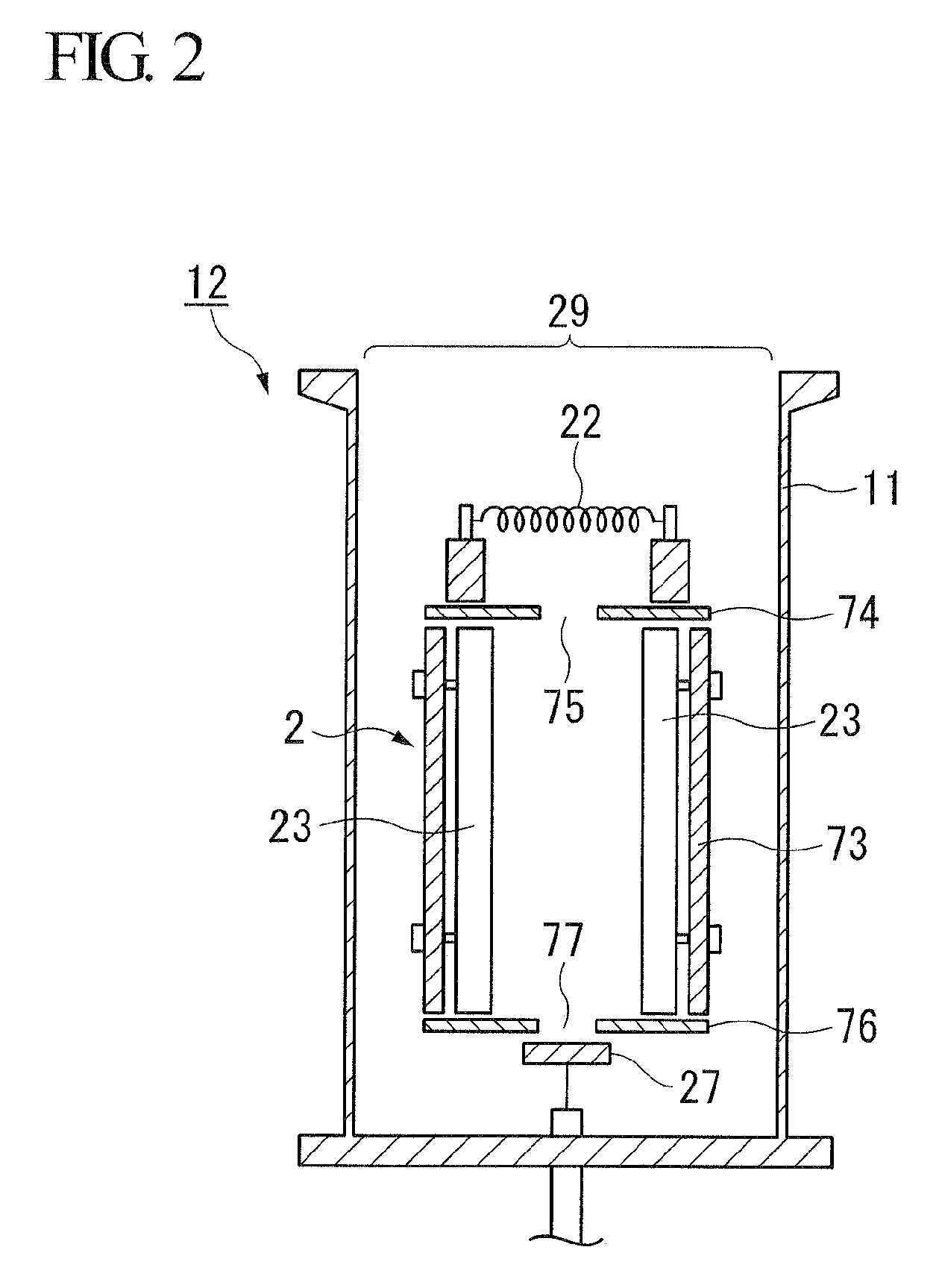
[0115]It is obvious that the higher the peak of the ion current value for the mass-to-charge ratio that is set for a specific gas in the memory portion 64 is, the larger the amount of the specific gas introduced into the chamber 52 of the etching apparatus 50 is. With the larger amount, the operating life of parts such as the ion source portion 22, the ion detection portion 27, and the like (hereinafter, referred to as expendable parts) becomes shorter. Furthermore, the longer the time during which a specific gas is being detected is, th...

third embodiment

(Parts Management Method)

[0127]Next is a description of a third embodiment of the present invention based on FIG. 8. The present embodiment is a parts management method in the case where the mass spectrometry unit 10 is attached to the etching apparatus 50. FIG. 8 is an exemplary record of serial numbers of the measurement portion and the pumps 80, 81, and specific gases.

[0128]The aforementioned expendable parts such as the ion source portion 22 and the ion detection portion 27 are parts with an operating life, and hence inevitably require replacement. In addition, the pumps 80, 81 of the differential exhaustion portion 20 require regular overhaul (hereinafter, regular overhaul work or replacement work of an expendable part will be referred to as “repair work,” and a part that requires overhaul or an expendable part that requires replacement will be referred to as a “part to be repaired.”). Incidentally, repair work of a part to be repaired is typically performed by a worker other t...

fourth embodiment

(Power Saving Method)

[0136]Next is a description of a fourth embodiment of the present invention based on a flow chart of FIG. 9. The present embodiment is a power saving method of the mass spectrometry unit 10 after completion of the etching process (after time T3 in FIG. 5).

[0137]As described above, during the introduction of a specific gas, the baking heaters 82a, 82b, 82c are used to heat the measurement portion 12 and the pumps 80, 81. At the same time of the specific gas introduction, the dilution gas supply portion 84 is used to flow a purge gas in order to dilute the specific gas flowing through the pumps 80, 81. However, if a specific gas is not introduced after, for example, completion of the etching process or the like, it is not necessary to heat the measurement portion 12 and the pumps 80, 81, and to purge the pumps 80, 81.

[0138]Nevertheless, if the operation of the heating of the measurement portion 12 and the pumps 80, 81, and the operation of the N2 purge of the pump...


PUM


Abstract

A mass spectrometry unit of the present invention includes a mass spectrometry portion that detects ion current values of a gas to be measured according to mass-to-charge ratio, to thereby measure partial pressures of the gas to be measured. The mass spectrometry unit further includes: a control portion for preliminary storing a record of a mass-to-charge ratio of a specific gas that decreases a function of a specific portion of the mass spectrometry unit, in which if an ion current value with the mass-to-charge ratio of the specific gas detected by the mass spectrometry portion is not less than a predetermined value, the control portion outputs a warning signal denoting a functional decrease in the specific portion.

Description

TECHNICAL FIELD[0001]The present invention relates to a mass spectrometry unit.[0002]Priority is claimed on Japanese Patent Application No. 2007-129408, the contents of which are incorporated herein by reference.BACKGROUND ART[0003]In a manufacturing process of semiconductor apparatuses and flat panel displays (FPDs), a variety of vacuum apparatuses are utilized. To perform a process management of the vacuum apparatuses, quadrupole mass analyzers are used. The mass analyzers are apparatuses for measuring partial pressures of a variety of substances included in the gas to be analyzed according to their mass-to-charge ratio (mass number / charge number). In addition, in recent years, the mass analyzers are used in a wide variety of fields such as an assaying of materials, an analysis of biopolymer compounds such as protein, and security. Therefore, there is an increasing demand for mass analyzers.[0004]A quadrupole mass analyzer energizes a filament as an ion source portion in a mass sp...

Claims


Application Information

Patent Timeline
Patent Type & Authority Patents(United States)
IPC IPC(8): H01J49/26B01D59/44
CPCH01J41/10G01N27/62G01L21/30H01J49/0027H01J49/42G01N27/623
Inventor NAKAJIMA, TOYOAKIKUROKAWA, YUJIROUYURI, TSUTOMUTANAKA, RYOTAYOSHIDA, SHUJI
Owner ULVAC INC
Learn More