Purge system for a substrate container

a technology of purging system and substrate, which is applied in the direction of packaging goods, instruments, printing, etc., can solve the problems of damage to delicate features, contamination and damage of reflective photomask (reticle) employed in euv photolithography, and the inability to provide transparent pellicle materials, etc., to achieve the effect of improving sealing conta

Active Publication Date: 2012-04-03
ENTEGRIS INC
View PDF51 Cites 33 Cited by
  • Summary
  • Abstract
  • Description
  • Claims
  • Application Information

AI Technical Summary

Benefits of technology

[0017]In certain embodiments, the bottom-opening pod has a pair of downwardly facing sealing flanges that directly interface with the nozzles on the tray. The sealing flanges support a portion of the weight of the pod and contents. The weight of the pod and contents loads and deflects the sealing flanges, thereby improving sealing contact between the sealing flanges and the nozzles. In an embodiment, the sealing flanges are combined with or integral with an elastomeric and / or resilient bushing or grommet that is received in an aperture extending through the door thus comprising a purge port assembly. The bushing has a bore therein that may receive a check valve component.
[0020]In certain embodiments a purging station provides a plurality of trays arranged in a stacked configuration for receiving the bottom-opening pods. The trays can be movable, for example swivelable in a horizontal direction to provide easy access to the bottom opening pods thereon.
[0022]According to yet another embodiment of the present invention, the bottom opening pod is provided with a means to continually inject pressurized, extremely clean dry air, denominated XCDA, into the hermetically sealed space of the reticle carrier and a means to exhaust the XCDA from the sealed space. A continuous purging in the hermetically sealed space in this manner serves to flush out contaminants and prevent haze formation or crazing on the mask / reticle therein. In preferred embodiments, a stack of swivelable trays will have purge lines to provide continuous purging of stored bottom-opening reticle pods.

Problems solved by technology

At his time, the art does not provide pellicle materials that are transparent to EUV.
Consequently, the reflective photomask (reticle) employed in EUV photolithography is susceptible to contamination and damage to a far greater degree than reticles used in conventional photolithography.
It is well known in the art that unnecessary and unintended contact of the reticle with other surfaces during manufacturing, processing, shipping, handling, transport or storage will likely cause damage to the delicate features on the patterned surface of the reticle due to sliding friction and abrasion.
Likewise, it is generally accepted by those skilled in the art that any particulate contamination of the surface of the reticle can potentially compromise the reticle to a degree sufficient to seriously affect the end products of processes that use such a flawed reticle.
For example, thin walled SMIF pods may experience wall movement due to altitude related pressure changes causing the trapped air inside the controlled environment to be displaced.
Dimensional changes of the container and its components due to pressure fluctuations can lead to compromising the sealing between cover and door of the carrier and incursion of particulates within the carrier.
Even with a perfectly sealed container, there is the possibility of air entering into the system when the reticle is removed from and replaced within the container during processing.
Water vapor condensing onto the patterned surface of the reticle can interfere with the optics just as a solid particulate would.
Some of these chemicals, such as acids for instance, are reactive with glass and can damage the reticle by etching it to create a haze on the patterned surface.
Prior art use of dessicants, for example, cannot ameliorate this problem because they cannot reduce the concentration of moisture to low enough levels to prevent salt (or crystal) formation.
Likewise, purging a reticle carrier with clean dry air (CDA) or other dry gas may not reduce the moisture concentration to the levels required to avoid crystal growth.
However, there is a limit to the number of such ‘cleans’ a reticle / mask can be subject to before resolution is degraded beyond functionality and the mask must be scrapped.
While desirable, it is generally infeasible to construct a hermetically sealed environment that is absolutely impervious to incursion by AMCs or other contaminants.
It is also infeasible to continuously purge the reticle carrier especially when the reticle and reticle carrier have to be transported or shipped.

Method used


Image

  • Purge system for a substrate container
  • Purge system for a substrate container
  • Purge system for a substrate container

Examples


Embodiment Construction

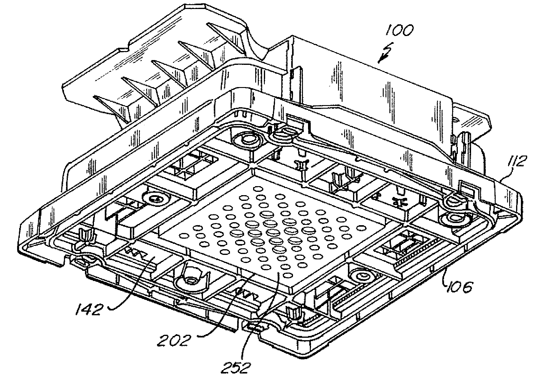
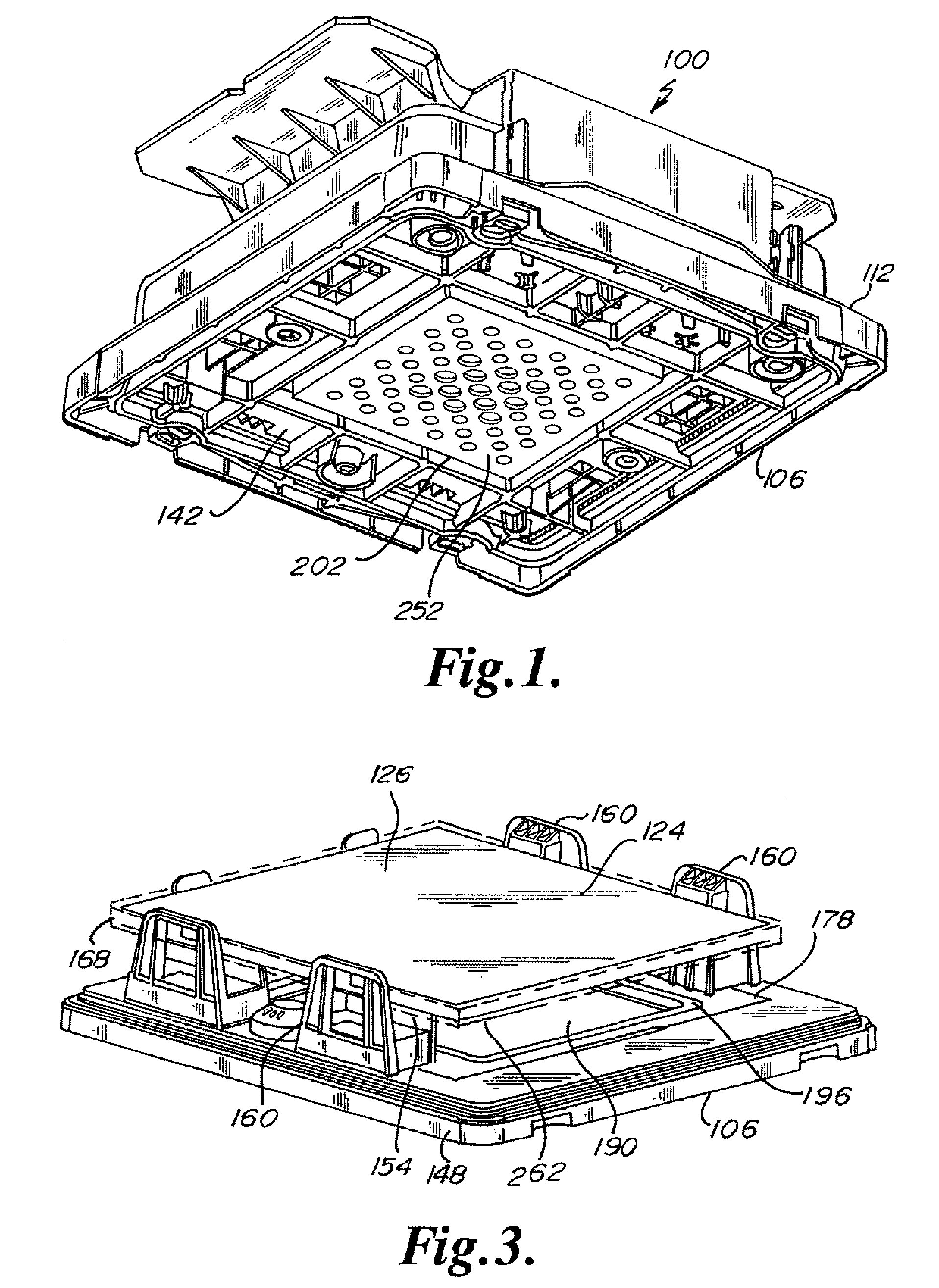
[0034]The accompanying figures depict embodiments of a bottom opening pod for holding substrates, specifically configured as a reticle carrier, and a purging station configured as a swivelable stack of trays providing a library of reticle pods. Any references to front and back, right and left, top and bottom, upper and lower, and horizontal and vertical are intended for convenience of description, not to limit the present invention or its components to any one positional or spatial orientation. “Substrate” when used herein refers to wafers, or reticles used in the manufacturing of semiconductors. Any dimensions specified in the attached Figures and this specification may vary with a potential design and the intended use of an embodiment of the invention without departing from the scope of the invention.

[0035]In FIGS. 1-4a, there is depicted a bottom-opening pod for substrates configured as a reticle carrier 100 equipped with purge capabilities according to a primary embodiment of th...


PUM

PropertyMeasurementUnit
wavelengthsaaaaaaaaaa
sizesaaaaaaaaaa

Abstract

A purging station with a substrate container receiving zone having at least one upwardly extending purging nozzle. The nozzle has a circular engaging lip. The substrate container has support means for at least one substrate and a purge port assembly that includes an externally facing sealing flange facing downward from the container. The sealing flange has a central aperture and a cantilevered flange portion that engages with the circular engaging lip of the nozzle. The weight of the substrate container on the nozzle carried by the canilevered portion of the flange causes bending of the flange for a resilient soft seal.

Description

RELATED APPLICATIONS[0001]This application claims the benefit of U.S. Provisional Patent Application No. 60 / 892,196, filed Feb. 28, 2007; this application is also related to U.S. patent application Ser. No. 11 / 396,949; filed Apr. 3, 2006, U.S. Provisional Application No. 60 / 668,189 filed Apr. 4, 2005, and U.S. Pat. No. 7,328,727 issued Feb. 12, 2008, all of which are incorporated herein in their entirety by reference.FIELD OF THE INVENTION[0002]The invention relates to substrate carriers used in semiconductor manufacturing and more particularly to transportable and shippable reticle / photomask carriers and purging systems for controlling the environment in such carriers.BACKGROUND OF THE INVENTION[0003]The processing of silicon wafers for semiconductor applications typically includes photolithography as one of the process steps. In photolithography, a wafer surface with a deposit of silicon nitride is coated over with a light-sensitive liquid polymer or photoresist and then selective...

Claims


Application Information

Patent Timeline
Patent Type & Authority Patents(United States)
IPC IPC(8): B65B31/00
CPCH01L21/67017H01L21/67353H01L21/67386H01L21/67393H01L21/67359Y10S414/14
Inventor TIEBEN, ANTHONY MATHIUSHALBMEIER, DAVID L.KOLBOW, STEVEN P.
Owner ENTEGRIS INC
Why Eureka
Try Eureka