Monolith filter apparatus and membrane apparatus, and method using same

Inactive Publication Date: 2012-04-03
VEOLIA WATER TECH INC
View PDF15 Cites 7 Cited by
  • Summary
  • Abstract
  • Description
  • Claims
  • Application Information

AI Technical Summary

Benefits of technology

[0024]It is a further object of this invention to provide such a filtration device that effectively utilizes most of its passageways by providing a low pressure drop flow path for filtrate between even the innermost passageways and an external filtrate collection zone associated with the device.
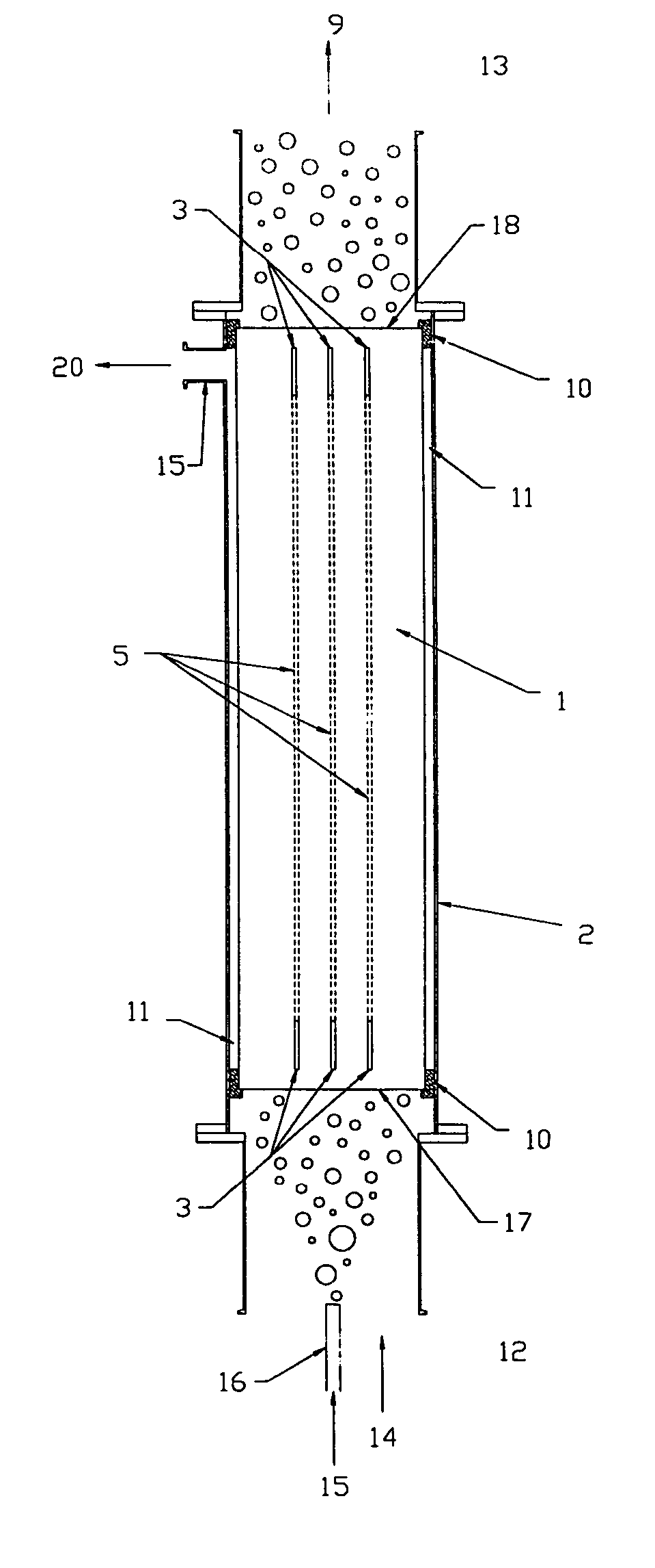
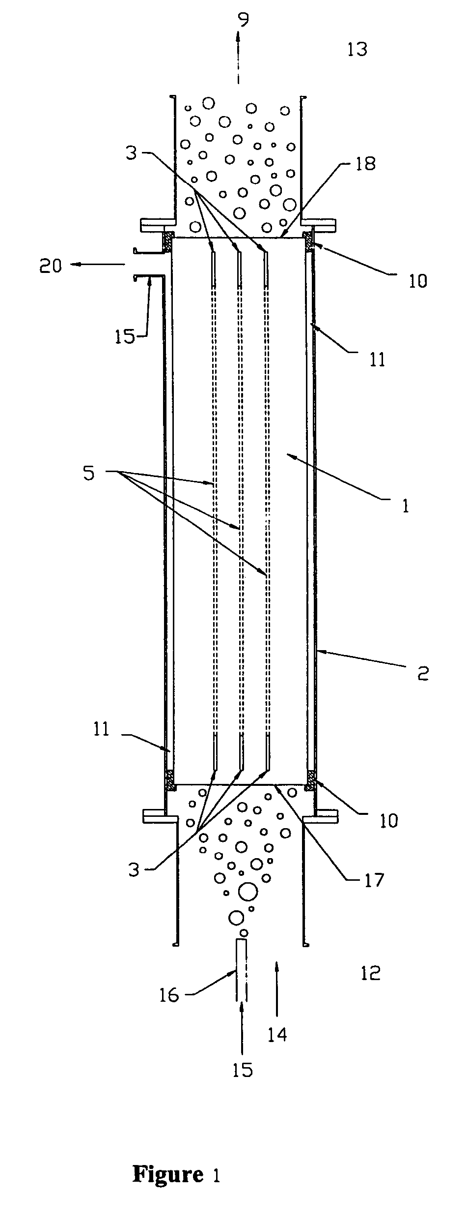
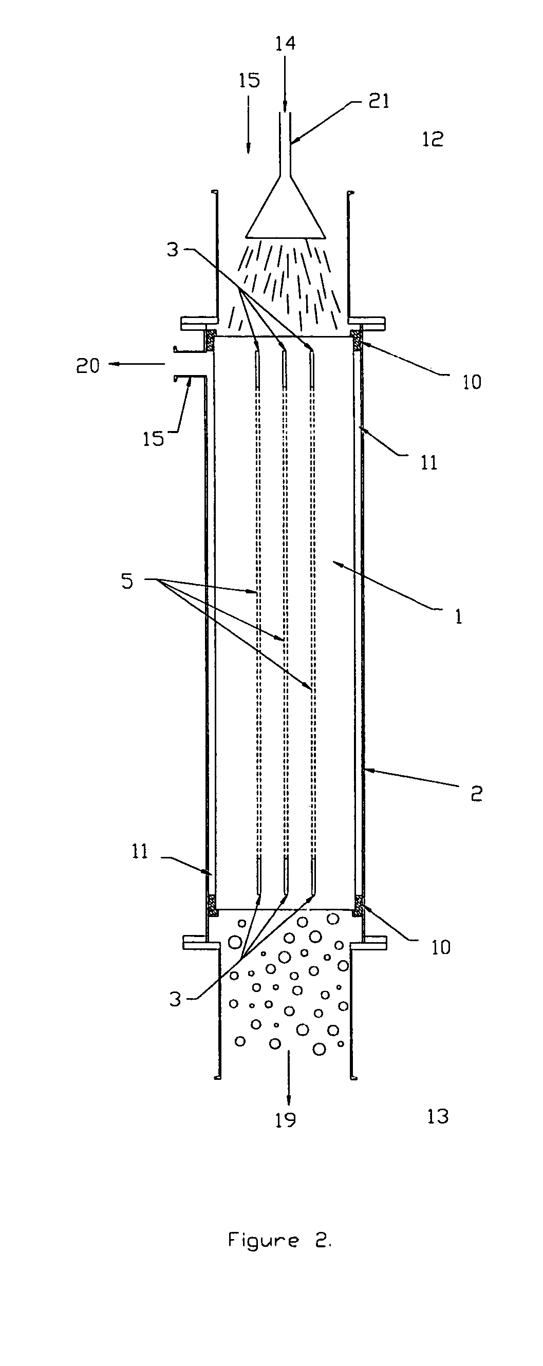
[0029]This invention results from the realization that the use of monolith structures for filtration devices has certain cost and technical limitations. Small diameter (or other characteristic dimension) monoliths generally need no filtrate conduits to achieve effective filtrate removal, yet are expensive to make, per unit filter area, and to install in housings. Large diameter monoliths can have greatly reduced costs, but require modifications to enhance filtrate removal from the inner passageways of the monolith.
[0030]This invention also results from the realization that the addition of entrained air bubbles in a liquid feedstock to be separated by such a monolith device can result in “slug flow” of gas and liquid in the monolith passageways, thereby greatly reducing concentration polarization and reducing the liquid feedstock flow rate required to maintain a high filtration rate.

Problems solved by technology

The downflow Taylor flow mode developed results in very high mass transfer between the liquid, gas and catalyst surface on the monolith passageway walls.
Nevertheless, no one has recognized that the use of large monolith-based membrane devices in the slug flow regime provides a very attractive operating mode in that membrane system complexity and cost can be significantly reduced.

Method used


Image

  • Monolith filter apparatus and membrane apparatus, and method using same
  • Monolith filter apparatus and membrane apparatus, and method using same
  • Monolith filter apparatus and membrane apparatus, and method using same

Examples


example 1

[0065]A slug flow membrane filter test loop for Fischer-Tropsch Slurry (FTS) catalyst / wax separation was assembled. A gas-lift membrane module was installed below a 200-liter heated feed tank. The membrane module was sparged at a bottom end face with nitrogen to create an upward flow, driven by buoyancy, and liquid from the feed tank was able to circulate to the inlet of the membrane module through a down comer leg. The total height of the two-phase fluid column from the gas inlet to the top of the column was approximately 120 cm. The membrane module assembly consisted of a CeraMem™ ceramic membrane element and a stainless steel housing. The membrane element had twelve 5-mm square feed passageways that were 308 mm long, resulting in a total membrane area of 0.073 m2. The passageways were coated with a nominal 10-nm pore size TiO2 UF membrane layer as the top layer in a multilayer membrane coating on a nominal 12-micron pore size, ca. 42% porosity recrystallized silicon carbide suppo...

example 2

[0080]In this example, a membrane bioreactor was tested in a university setting, using sanitary wastewater taken from the university's wastewater treatment facility. The test system consisted of a biological oxidation tank with a hydraulic residence time (HRT) of about 4 hrs and a mixed liquor suspended solids (MLSS) level of about 10 g / l. Two membrane types were tested. First was an X-Flow (Enschede, NL) multi-tubular polymeric membrane module. The module contained seven (7) tubular elements, each with an 8 mm i.d., potted into a tubular bundle of 1000 mm length. The membrane pore size was nominally 0.03 micron. The second was a CeraMem membrane element. The monolith element contained 9 square passageways, each 5 mm on a side. The length of the test element was 346 mm, and the nominal membrane pore size the α-alumina MF membrane was 0.1 micron. The porous monolith support was the same as that used in Example 1.

[0081]Tests were conducted in an external airlift configuration, in whic...


PUM

PropertyMeasurementUnit
Lengthaaaaaaaaaa
Fractionaaaaaaaaaa
Timeaaaaaaaaaa

Abstract

A filtration apparatus that separates a liquid feedstock mixed with a gas into filtrate and retentate, the apparatus including at least one filtration device comprised of at least one monolith segment of porous material that defines a plurality of passageways extending longitudinally from a feed face of the structure to a retentate end face. The filtration device contains at least one filtrate conduit within it for carrying filtrate toward a filtrate collection zone, the filtrate conduit providing a path of lower flow resistance than that of alternative flow paths through the porous material of the device. The filtration device can also be utilized as a membrane support for a device for microfiltration, ultrafiltration, nanofiltration, reverse osmosis, or pervaporation. Also disclosed is a method for using such a filtration apparatus.

Description

RELATED CASES[0001]This application is a continuation-in-part of U.S. Ser. No. 10 / 261,107, filed Sep. 30, 2002 now U.S. Pat. No. 6,767,455, “Airlift Membrane Device and Membrane Bioreactor and Bioreactor Process Containing Same”, by Robert L. Goldsmith, which is a utility application claiming priority of provisional application U.S. Ser. No. 60 / 404,944 filed on Aug. 21, 2002.[0002]The results in Example 1 of this invention were obtained with Government support under the SBIR Phase I Grant DE-FG02-03ER83621 awarded by the Department of Energy. The Government has certain rights in this invention for the application to the removal of catalyst particulates from Fischer-Tropsch catalyst / wax slurries.BACKGROUND OF THE INVENTION[0003]Filtration and membrane processes for liquid phase separations include cross-flow filtration, microfiltration, ultrafiltration, nanofiltration, and reverse osmosis. Each of these processes can have the filtration rate (membrane flux) reduced by concentration p...

Claims


Application Information

Patent Timeline
IPC IPC(8): B01D63/06B01D69/04B01D61/00B01D69/10C12M1/40B01D61/14B01D61/18B01D61/20B01D63/00B01D65/02B01D65/08B01D71/02C02F1/44C02F3/12C02F3/28
CPCB01D61/18B01D63/066B01D65/02B01D65/08C02F1/444C02F3/1273B01D2321/12B01D2321/16B01D2321/162Y02W10/10
Inventor GOLDSMITH, ROBERT L.
Owner VEOLIA WATER TECH INC
Why Eureka
Try Eureka