
PVD coated substrate

a substrate and coating technology, applied in boring/drilling components, magnetic recording, electrical equipment, etc., can solve the problems of reducing the service life of tools, so as to achieve the effect of increasing the chemical inertness, high hardness, and low friction coefficien

Inactive Publication Date: 2012-05-08
SHEFFIELD HALLAM UNIVERSITY
View PDF15 Cites 9 Cited by
  • Summary
  • Abstract
  • Description
  • Claims
  • Application Information

AI Technical Summary

Benefits of technology

"The present invention provides a new type of coating for cutting tools that has high hardness, low friction, and increased chemical inertness. This coating is made up of a repeating bilayer that alternates between layers with different compositions. The coating is made using a PVD technique and can be applied to a variety of substrates that are exposed to frictional forces. The coating can be used in cutting tools, mechanical engine parts, and other applications where high friction is involved. The coating helps to reduce friction and wear during sliding wear, and also prevents chemical reaction between the coated surface and the workpiece material. The method of manufacturing the cutting tool involves pretreating the tool prior to coating it with the multilayer coating."

Problems solved by technology

For example, highly used carbon-based composite, workpiece materials laminated with aluminum alloy sheeting, are so abrasive that unprotected, standard cutting tools are capable of cutting a relatively small portion only of the workpiece material.
This is further complicated by the orientation of the top and bottom layers when “through” drilling the composite materials.
The cutting edges of such tools are blunted very rapidly after, for example only two drilling operations, whereby the tool is no longer suitable for use and must be discarded.
Both these types of alloy exhibit low thermal conductivity resulting in intensive heat generation at the cutting region.
Consequently, it is a common problem for the geometry of the cutting tool to alter, following only small or moderate periods of cutting of these types of alloy, thereby deteriorating the cutting performance.
However, such coatings whilst addressing the problems of wear resistance are still susceptible to micro welding and workpiece material pick-up due to the intensified chemical interaction between the coating and the workpiece material resulting from friction and hence heat generation at the tool-workpiece interface.

Method used


Image

  • PVD coated substrate
  • PVD coated substrate
  • PVD coated substrate

Examples


example 1

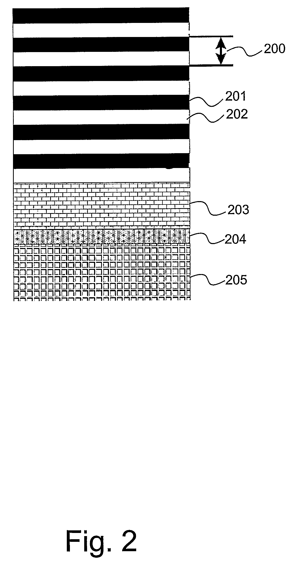
Nanoscale Superlattice Multilayer Coating

[0053]A deposition procedure for the production of a nanoscale, compositionally modulated, multilayer structured coating of (VMe)(CN) / (MeV)(CN), where Me is AlTi is described.

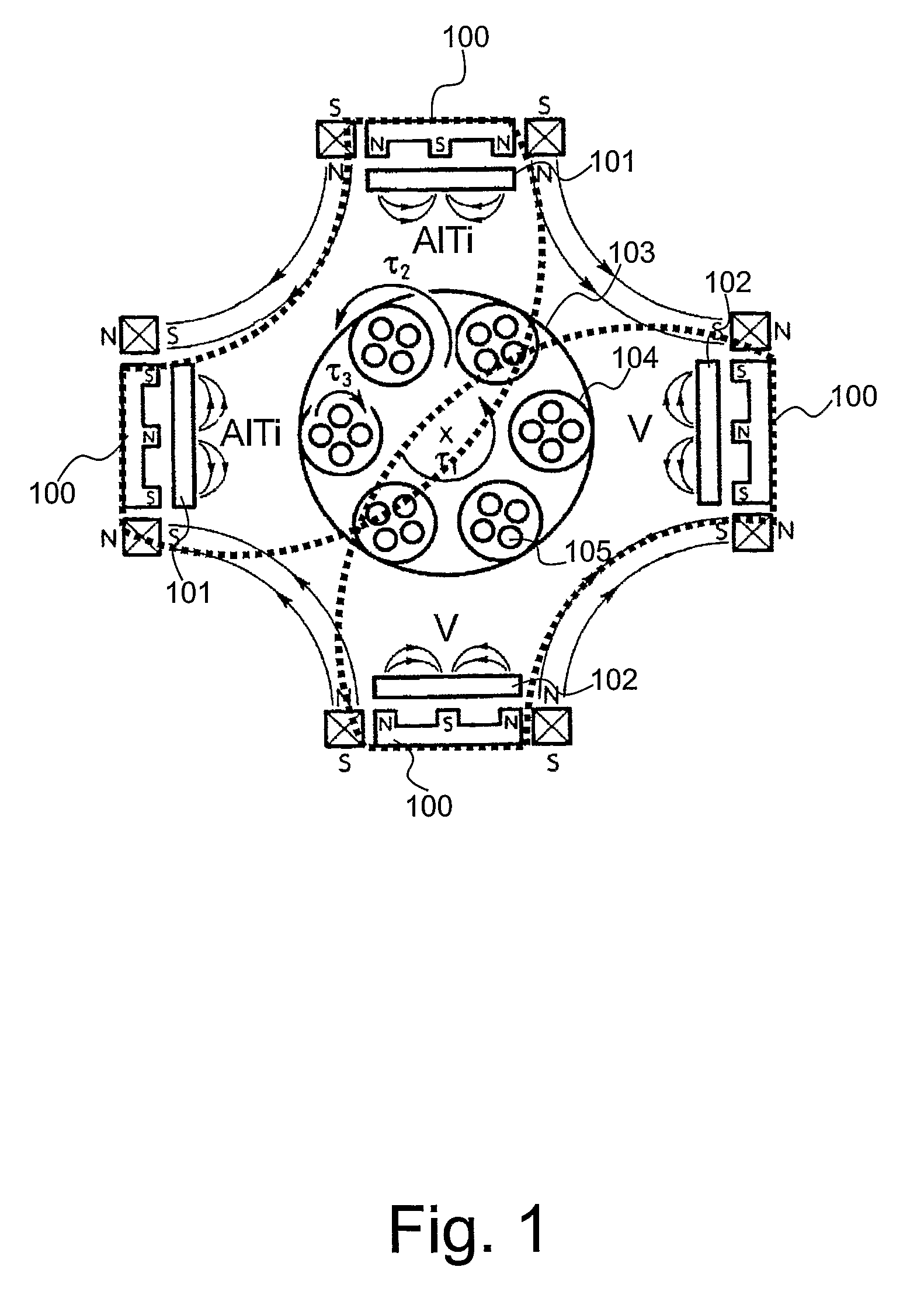
[0054]The (VAlTi)(CN) / (AlTiV)(CN) superlattice nanoscale multilayer coating is deposited by reactive sputtering of two pairs of AlTi 50:50 at. % and V 99.8% pure targets opposing each other in a common Ar+N2+CH4 atmosphere as illustrated in FIG. 1 herein.

[0055]The necessary carbon atoms can be supplied by other carbon containing reactive gasses such as C2H2 or by evaporation or sputtering of a solid graphite target.

[0056]The metal atoms in the film can be produced not only by various types of sputtering techniques but also by evaporation methods such as arc evaporation.

[0057]The nanoscale multilayer coating deposition process utilized in this example comprised three major steps: surface pretreatment (etching), base layer deposition and nanoscale multilayer deposition.

[00...


PUM

PropertyMeasurementUnit
thicknessaaaaaaaaaa
thicknessaaaaaaaaaa
thicknessaaaaaaaaaa

Abstract

A PVD coating is disclosed, and in particular a nanoscale multilayer superlattice PVD coating comprising high hardness, a low friction coefficient and increased chemical inertness. The multilayer coating comprises a repeating bilayer represented by (VxMe(i-x))CyN(i-y) / (MezV(1-z))CyN(i-y) where 0.1≦x≦0.9; 0.01<y<0.99 and 0.1≦z≦0.9 and Me is a substantially pure metal or a metal alloy. The composition of the coating through the layers alternates from layer to layer according to a V-rich layer and a Me-rich layer modulated sequence. Vanadium is incorporated within the layer composition and has been found to act as a lubricating agent during sliding wear. Carbon, also incorporated within the coating, serves to further stabilize the friction coefficient thereby increasing the chemical inertness between cutting tool and workpiece material.

Description

RELATED / PRIORITY APPLICATION[0001]This application is a National Phase filing regarding International Application No. PCT / GB2006 / 001509, filed on Apr. 25, 2006. International Application No. PCT / GB2006 / 001509 claims priority from British Application No. 0508485.0, filed on Apr. 27, 2005.FIELD OF THE INVENTION[0002]The present invention relates to a coating for a substrate and, in particular although not exclusively, to a coating for a cutting tool exhibiting high hardness, low friction and increased chemical inertness.BACKGROUND TO THE INVENTION[0003]There is a continued increase in the requirement for highly durable cutting tools in response to the demand for and manufacture of more exotic, sophisticated high strength, structural materials used particularly within the aerospace and automotive industries. These materials bring substantial benefits to these industries due to their very high strength to low weight ratio.[0004]For example, highly used carbon-based composite, workpiece ...

Claims


Application Information

Patent Timeline
Patent Type & Authority Patents(United States)
IPC IPC(8): B32B9/00C23C28/02
CPCC23C30/00H01J37/3467C23C28/42C23C28/044Y10T428/265Y10T428/24975Y10T407/27Y10T408/78Y10T428/31678C23C14/0664
Inventor HOVSEPIAN, PAPKENEHIASARIAN, ARUTIUN P.
Owner SHEFFIELD HALLAM UNIVERSITY
Learn More