Rivet fastening system

Active Publication Date: 2012-11-27
LEMIEUX DAVID L
View PDF19 Cites 25 Cited by
  • Summary
  • Abstract
  • Description
  • Claims
  • Application Information

AI Technical Summary

Benefits of technology

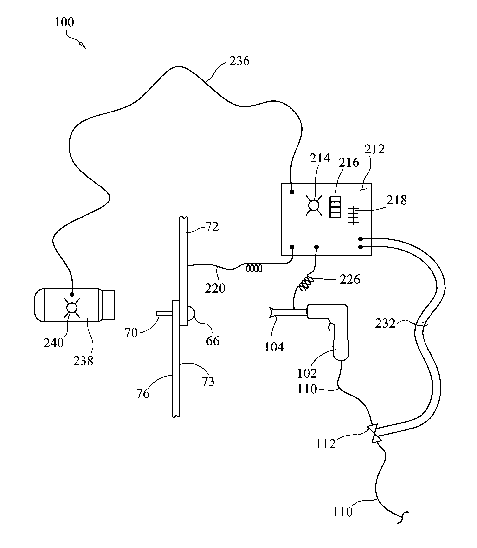
[0021]One object of preferred embodiments of the invention is to measure the formed rivet head during the rivet driving process and through a feedback control process disable or stop the rivet gun the moment the rivet head achieves the desired set tolerance. In this embodiment, an automated control process allows both operators to focus on holding their tools orthogonal to the work surface and not be concerned about under-driving or over-driving the rivet. Another object of preferred embodiments of the invention is to provide a means for communicating the stage of the rivet driving process to both rivet-gun and bucking operators by means of light, e.g., light-emitting diode (LED) indicators, with at least one LE

Problems solved by technology

Although the cost of installing one rivet is small, installing the great number of rivets used in airplane manufacture represents a large percentage of the total cost of any airplane.
For example, “It is often difficult to consistently set rivets to meet tolerances but it is extremely difficult to consistently set rivets to an optimal tolerance.”
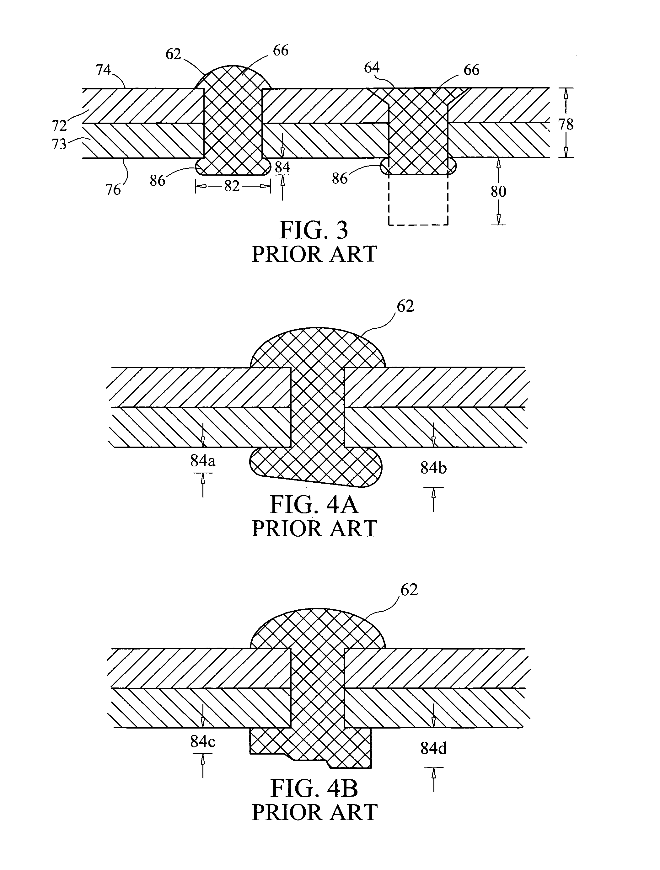
If the rivet has been under-driven leaving the head height too high, additional driving is needed (although due to work hardening of the rivet material, rivet holding strength for rivets driven in repeated driving stages is often reduced).
Over-driven rivets require removal, which is a time consuming process that can often damage the work and sometimes requires using an oversized replacement rivet having a different setting tolerance.
Over-driven rivets often blemish or bend the work, sometimes causing costly rework or irreparable damage.
This communication from the bucker to the rivet gun operator to “stop riveting” is difficult to achieve because no adequate means to affect this communication, during the loud riveting process, is proposed.
Furthermore, due to reaction times of both operators and the fact that a rivet gun typically hammers at rates exceeding 20 Hertz, it is unlikely that these methods could achieve consistent desired rivet setting tolerance control.
Most importantly, if the rivet gun were not immediately stopped at the moment the bucker visually identified rivet set completion, the additional impacting forces from the rivet gun would be imparted through the rivet to the anvil face and from the set-rivet through the work to the spindle's feet result

Method used


Image

  • Rivet fastening system
  • Rivet fastening system
  • Rivet fastening system

Examples


working example

[0176]Referring to FIG. 22, a digital recording of operation of a prototype of system 100 using an oscilloscope shows bucking bar tool-to-work contact time using a preferred embodiment of bucking bar 238; the drawing represents bar 238 dynamic response to a rivet gun “hammer” cycle. Also, the recording shows clear signs of switch chatter 371 (rapid opening and closing of contacts) indicative of extreme vibration and / or shock between anvil face 300 and rivet shank end 70. Contact bounce or oscillation of movable contact upon closure of circuit was present as indicated by first contact bounce signature 373. The “switch” in this case was the make or break when the bucking bar was in contact or bounced off (not in contact) with the forming rivet head; respectively. When in contact, a voltage was detected and when not in contact, no voltage was detected. The rivet gun “hammer-blow” was indicated by first falling edge hammer signal 375. The time interval the anvil face 300 was “bucked-off...


PUM

PropertyMeasurementUnit
Timeaaaaaaaaaa
Forceaaaaaaaaaa
Pressureaaaaaaaaaa

Abstract

A system and method for rivet setting comprising a micro-adjustable bucking bar coupled to a control system that measures the rivet head during the rivet setting process and stops the rivet gun when the rivet head achieves a desired head height above the work surface. In preferred embodiments, the control system also communicates the stage of the rivet driving cycle to the operators to expedite the rivet driving process.

Description

CROSS-REFERENCE TO RELATED APPLICATIONS[0001]Not ApplicableSTATEMENT REGARDING FEDERALLY SPONSORED RESEARCH OR DEVELOPMENT[0002]Not ApplicableTHE NAMES OF THE PARTIES TO A JOINT RESEARCH AGREEMENT[0003]Not ApplicableINCORPORATION-BY-REFERENCE OF MATERIAL SUBMITTED ON A COMPACT DISC[0004]Not ApplicableBACKGROUND OF THE INVENTION[0005]This invention relates to a system and method for fastening rivets and / or using process indicators to communicate to operators the stage of each rivet during a rivet setting cycle. In particular, the invention relates to a system and method that relies on a micro-adjustable switching mechanism that is used as part of a feedback control system to achieve rivet setting tolerances by measuring in real-time or near-real-time the rivet's driven head (sometimes called the upset head or shop head) height while the control system also controls rivet gun operation and communicates the rivet driving-cycle stage to the rivet setting operator(s).[0006]Riveting produ...

Claims


Application Information

Patent Timeline
IPC IPC(8): B21D39/00B23P21/00B21J15/32
CPCB21J15/10B21J15/02B21J15/105B21J15/36B21J15/28Y10T29/5377Y10T29/49943Y10T29/5307
Inventor LEMIEUX, DAVID L.
Owner LEMIEUX DAVID L
Why Eureka
Try Eureka