Optical clock

a technology of optical clocks and pulses, applied in optics, instruments, electromagnetic transmission, etc., can solve the problems of inconvenient operation, high physical complexity of clocks, and inability to meet the needs of practical applications outside the laboratory, so as to reduce frequency-noise and time-jitter in optical clock pulses

Active Publication Date: 2013-02-26
QINETIQ LTD
View PDF18 Cites 2 Cited by
  • Summary
  • Abstract
  • Description
  • Claims
  • Application Information

AI Technical Summary

Benefits of technology

[0003]Optical clocks having the above characteristics typically comprise modelocked lasers, for example a diode-laser modelocked in an external cavity. Such a device requires significant human intervention in order to set the device up and keep it running in a desired operational state. Such devices are therefore highly unsuited to practical applications outside the laboratory. Clocks based on modelocked fibre-lasers (see for example W. Ng et al, Journal of Lightwave Technology, 22, pp 1953-1961, August 2004) provide some degree of physical and operational robustness, however such a device requires a feedback arrangement to compensate for drift in repetition rate resulting from path length changes caused by temperature fluctuations in the surrounding environment. Such clocks are therefore physically complex. Furthermore, modelocked lasers comprise very specialised components, making clocks based on them unsuitable for mass-production. Another problem associated with clocks based on modelocked lasers (including modelocked fibre-lasers) is that adjustment of the repetition rate of the optical clock pulses is complicated as this involves careful adjustment of the laser cavity length.
[0005]An optical clock of the invention is simple in terms of construction, is robust and may be assembled from readily-available components. Such a clock may operate indefinitely without human intervention. Furthermore, an optical clock of the invention provides for simple (electronic) adjustment of the repetition rate of the optical clock pulses. Pulse compression occurs by a mechanism which includes self phase-modulation (SPM). Stimulated Brillouin scattering (SBS), which typically occurs within optical fibres at peak-powers also associated with SPM, and which can reduce optical power output and stability from the optical fibre, is inhibited as a result of the linewidth of the laser source and the optical pulses. Unlike optical clocks based on modelocked lasers, precise alignment of the components of a clock of the invention is not required. Optical pulses output from the optical fibre have low timing-jitter and may be as short as 10-15 ps as a result of compression by SPM, or SPM and group velocity dispersion. Optical pulses output from the optical fibre may be used directly as optical clock pulses, or they may be manipulated in some way (e.g. pulse-picked) to produce a series of optical clock pulses.
[0008]In embodiments in which the laser source comprises a laser oscillator and modulating means arranged to cooperate with the laser oscillator to produce phase-modulated radiation, timing-jitter in the optical clock pulses may be reduced by arranging the modulating means to provide phase-modulation with a minimum modulation-depth consistent with inhibiting SBS within the optical fibre.
[0011]To reduce the output power required of the laser source, an optical amplifier (e.g. an erbium-doped fibre-amplifier (EDFA)) may be used to amplify the series of optical pulses prior to compression by the optical fibre. The amount of amplified spontaneous emission entering the optical fibre from the fibre may be reduced by using a circulator at the end of the optical fibre into which the series of phase-modulated optical pulses is introduced, the circulator being coupled to a Bragg grating having a suitable grating-pitch.
[0015](iii) passing the series of optical pulses through optical fibre to compress the optical pulses,the linewidth of the laser source being sufficient to inhibit stimulated Brillouin scattering (SBS) of the optical pulses within the optical fibre.

Problems solved by technology

Low timing jitter is desirable because errors in sampling time result in inaccurate conversion of a rapidly changing analogue signal.
Such devices are therefore highly unsuited to practical applications outside the laboratory.
Such clocks are therefore physically complex.
Furthermore, modelocked lasers comprise very specialised components, making clocks based on them unsuitable for mass-production.
Another problem associated with clocks based on modelocked lasers (including modelocked fibre-lasers) is that adjustment of the repetition rate of the optical clock pulses is complicated as this involves careful adjustment of the laser cavity length.
Stimulated Brillouin scattering (SBS), which typically occurs within optical fibres at peak-powers also associated with SPM, and which can reduce optical power output and stability from the optical fibre, is inhibited as a result of the linewidth of the laser source and the optical pulses.

Method used


Image

  • Optical clock
  • Optical clock
  • Optical clock

Examples


Embodiment Construction

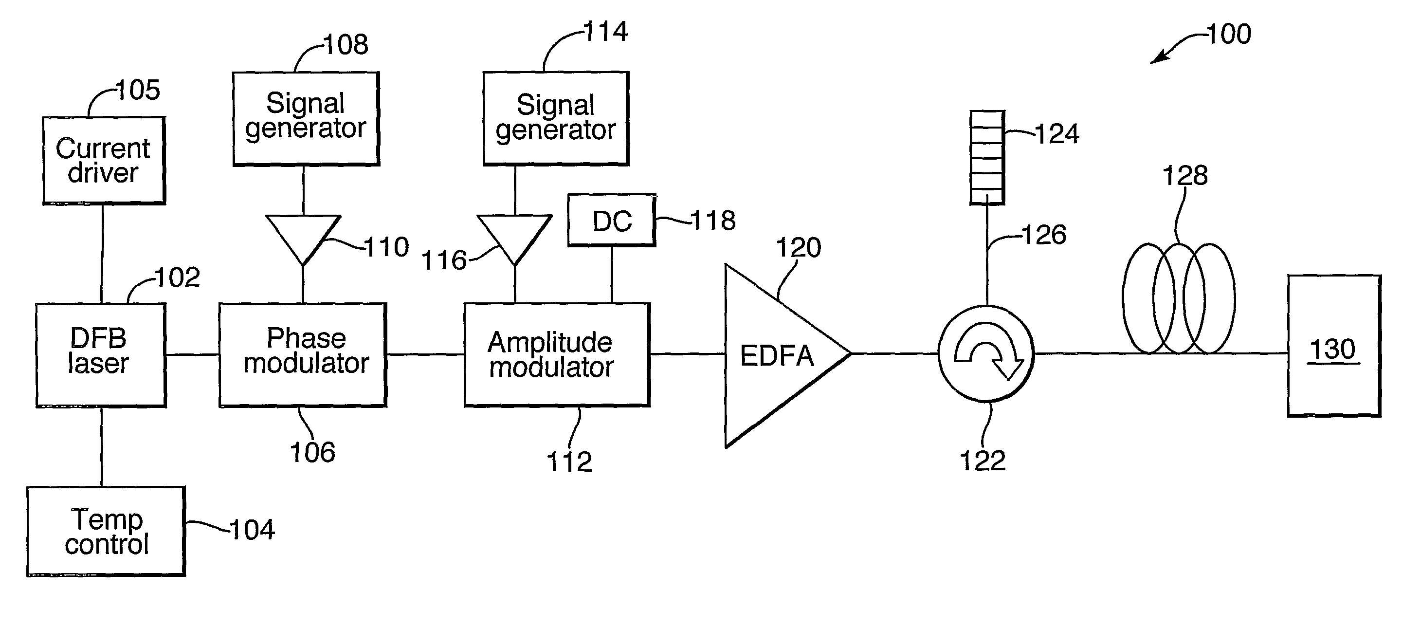
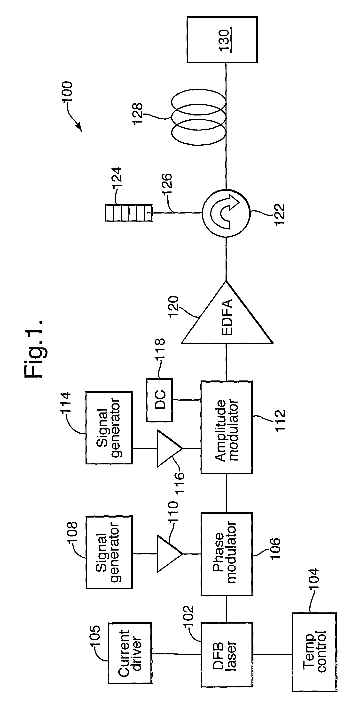
[0025]In FIG. 1, an optical clock 100 of the invention comprises a DFB laser oscillator 102 which is temperature-stabilised by a temperature-controller 104 to stabilise the output wavelength of the DFB laser 102. Output from the DFB laser 102 passes to a phase-modulator 106 and then to a push / pull-type amplitude-modulator 112. Modulators 106, 112 are standard devices, based on gallium arsenide for example, and are driven by signal generators 108, 114 the output signals of which are amplified by amplifiers 110, 116 before being applied to the modulators 106, 112. Signal generator 114 is an HP® model 83711A. A DC supply 118 provides a DC bias to the amplitude-modulator 112. Optical output from the amplitude-modulator 112 is in the form of a series of optical pulses which are amplified by an erbium-doped fibre-amplifier (EDFA) 120 and input to an optical fibre 128 via a circulator 122 which is coupled to a Bragg grating 124 by a short length of optical fibre 126. The optical fibre 128 ...


PUM

PropertyMeasurementUnit
lengthaaaaaaaaaa
frequencyaaaaaaaaaa
frequencyaaaaaaaaaa

Abstract

An optical clock comprises a laser oscillator and modulating means arranged to cooperate with the laser oscillator to produce a series a series of phase-modulated optical pulses. The optical clock further comprises an optical fiber arranged to provide compression of the optical pulses, and may also comprise a step-recovery diode arranged to pulse-pick pulses output from the fiber to produce a series of optical clock pulses, depending on the mode of operation of the modulating means. Phase-modulation is carried out a frequency which provides sufficient linewidth broadening to inhibit stimulated Brillouin scattering within the optical fiber. An optical clock of the invention provides a robust and reliable alternative to clocks based on modelocked lasers, and may be assembled from inexpensive, commonly-available components. The repetition rate of a clock of the invention may easily be adjusted by electronic means. Unlike many modelocked lasers, a clock of the invention does not require precise optical alignment.

Description

BACKGROUND OF THE INVENTIONSummary[0001]The invention relates to optical clocks.[0002]Optical clocks which produce ultra-short optical pulses with low timing jitter are of interest in applications such a high bit-rate optical communication and photonic analogue-to-digital conversion (ADC). In the case of photonic ADC, ultra-short optical clock pulses are required so that an analogue signal can be sampled at a series of discrete times, avoiding integration over a range of signal values each time the analogue signal is sampled. Low timing jitter is desirable because errors in sampling time result in inaccurate conversion of a rapidly changing analogue signal.[0003]Optical clocks having the above characteristics typically comprise modelocked lasers, for example a diode-laser modelocked in an external cavity. Such a device requires significant human intervention in order to set the device up and keep it running in a desired operational state. Such devices are therefore highly unsuited t...

Claims


Application Information

Patent Timeline
Patent Type & Authority Patents(United States)
IPC IPC(8): G02F1/01
CPCH01S3/0057H01S3/06754H01S3/0085H01S3/06725H01S2301/02
Inventor MCDONALD, GREGOR JOHN
Owner QINETIQ LTD
Why Eureka
Try Eureka