

Composition for improving efficiency of drug delivery
a drug delivery and efficiency technology, applied in the field of drug delivery, can solve the problems of poor drug diffusion through the tissue, limited drug delivery methods, and ineffective drug delivery methods, etc., to achieve the effect of improving the infusion of pharmaceutical agents, minimizing backflow of pharmaceutical agents, and low resistan
- Summary
- Abstract
- Description
- Claims
- Application Information
AI Technical Summary
Benefits of technology
Problems solved by technology
Method used
Image

Examples
example 1
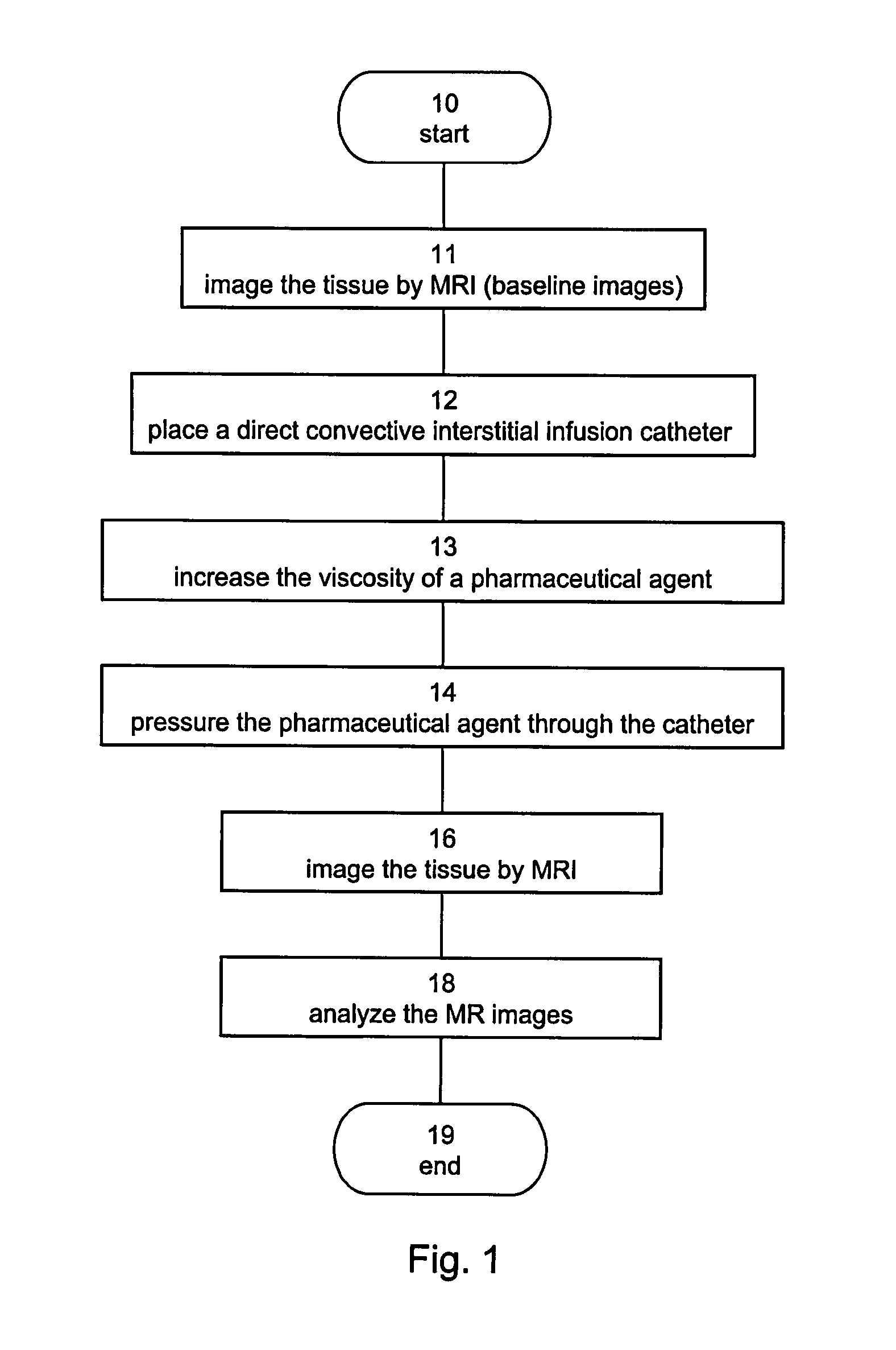
[0213]In accordance with various exemplary embodiments of the present invention, rats subjected to CED treatment in the brain were imaged by MRI. The MR images were analyzed and used to monitor the convection of the administrated agent and to determine the cytotoxic response of the treated tissue.
Methods
Experiment Design
[0214]Solutions containing combinations of Cremaphore, Taxol®, Carboplatin, Ethanol, sucrose and human serum albumin (HSA) in different concentrations were mixed with Gd-DTPA (1:70). The resultant solution was infused into the striatum of normal Sprague-Dawley (SD) rats (males, 250-300 grams). T1-weighted MR images were acquired immediately post treatment to assess the extent of convection. Additionally, T2-weighted and diffusion-weighted MR images were acquired 24 hours post treatment to assess the response of the tissue and its correlation to the extent of convection. Some rats were monitored by MRI for an additional period of several days to demonstrate the subseq...
example 2
[0259]In accordance with various exemplary embodiments of the present invention, high viscosity infusates were used for distributing Iron Oxide (IO) nano particles in rat brain by CED.
Methods
[0260]The impact of enhanced viscosity on CED of large particles was tested for 10 nano-particles (20 nm dry size, 70 nm wet size).
Experiment 1
[0261]A low viscosity solution consisting of IO biocompatible and biodegradable particles suspended in saline and a high viscosity solution, consisting of the same concentration of IO particles, suspended in a saline solution containing HSA were infused into the rat striatum. The infusion was performed at a rate of 1 μl / min for duration of 30 minutes. Immediate monitoring of CED formation and extent was performed using gradient echo MR images.
Experiment 2
[0262]IO particles, as in Experiment 1 were covered with Dextrane to increase viscosity and infused into rat brain. The infusion was performed at a rate of 4 μl / min for duration of 15 minutes. 24 rats wer...
experiment 1
[0263]FIGS. 11A-B show Sagittal slices of gradient echo MRI acquired immediately post infusion with the low viscosity IO infusate (2 rats, FIG. 11A) and the high viscosity IO infusate (2 rats, FIG. 11B). The presence of IO particles is shown in the gradient echo MR images as a dark region near the catheter tip.
[0264]As shown in FIGS. 11A-B, although the two solutions (low and high viscosity) had an identical number of IO particles, the CED of the low viscosity IO infusate resulted in a dark region which is significantly smaller (about 1-2 mm in diameter) compared to the artifact caused by using the viscous infusate (4 mm diameter). It is therefore demonstrated that the efficacy and extent of convection strongly depends on the viscosity of the infused composition.
PUM
 Abstract
Description
Claims
Application Information