Plastic optical fiber cable and method of transmitting signal

a technology of optical fiber cable and plastic fiber, which is applied in the direction of cladded optical fibre, instruments, optical elements, etc., can solve the problems of reducing the optical performance of the pof, and the description of high-melting point nylon resin as unsuitable as a coating material, etc., to achieve excellent long-term heat resistance, low cost, and low cost

Active Publication Date: 2013-04-16
MITSUBISHI CHEM CORP
View PDF18 Cites 4 Cited by
  • Summary
  • Abstract
  • Description
  • Claims
  • Application Information

AI Technical Summary

Benefits of technology

[0040]According to the present invention, it is possible to provide a plastic optical fiber cable having little increase in transmission-loss under a high-temperature environment, and being excellent in long-term heat resistance, highly flexible and easily handled, and to provide a method of transmitting a signal using this cable.

Problems solved by technology

However, the quartz-based optical fiber is expensive and low in processability.
However, when a polyamide resin (nylon resin) is used as a material for a coating layer of a POF cable, the following problems are raised.
Furthermore, some reports describe that when a nylon resin such as nylon 66 having a relative high melting point is applied onto the periphery of a POF as a coating, excessive stress is applied to the POF, significantly diminishing optical performance of the POF.
Thus a high-melting point nylon resin is described to be unsuitable as a coating material for a POF.
Moreover, in the case where a nylon resin having a high bending-elastic modulus such as nylon 66 is applied to the periphery of a POF as a coating, processability and handling of the POF cable become difficult when it is laid and a plug (ferrule) is provided.
Damage to the POF cable increased and productivity decreased, in some cases.
However, when a nylon resin having a high bending-elastic modulus such as nylon 66 is applied to the periphery of a bare POF as a coating, processability and handling of the POF cable become difficult when it is laid and a plug (ferrule) is provided.
Damage to the POF cable increased and productivity decreased, in some cases.

Method used


Image

  • Plastic optical fiber cable and method of transmitting signal
  • Plastic optical fiber cable and method of transmitting signal
  • Plastic optical fiber cable and method of transmitting signal

Examples


example 1a

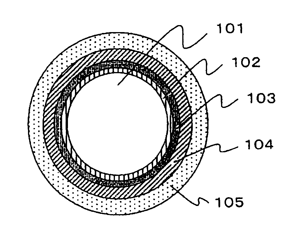
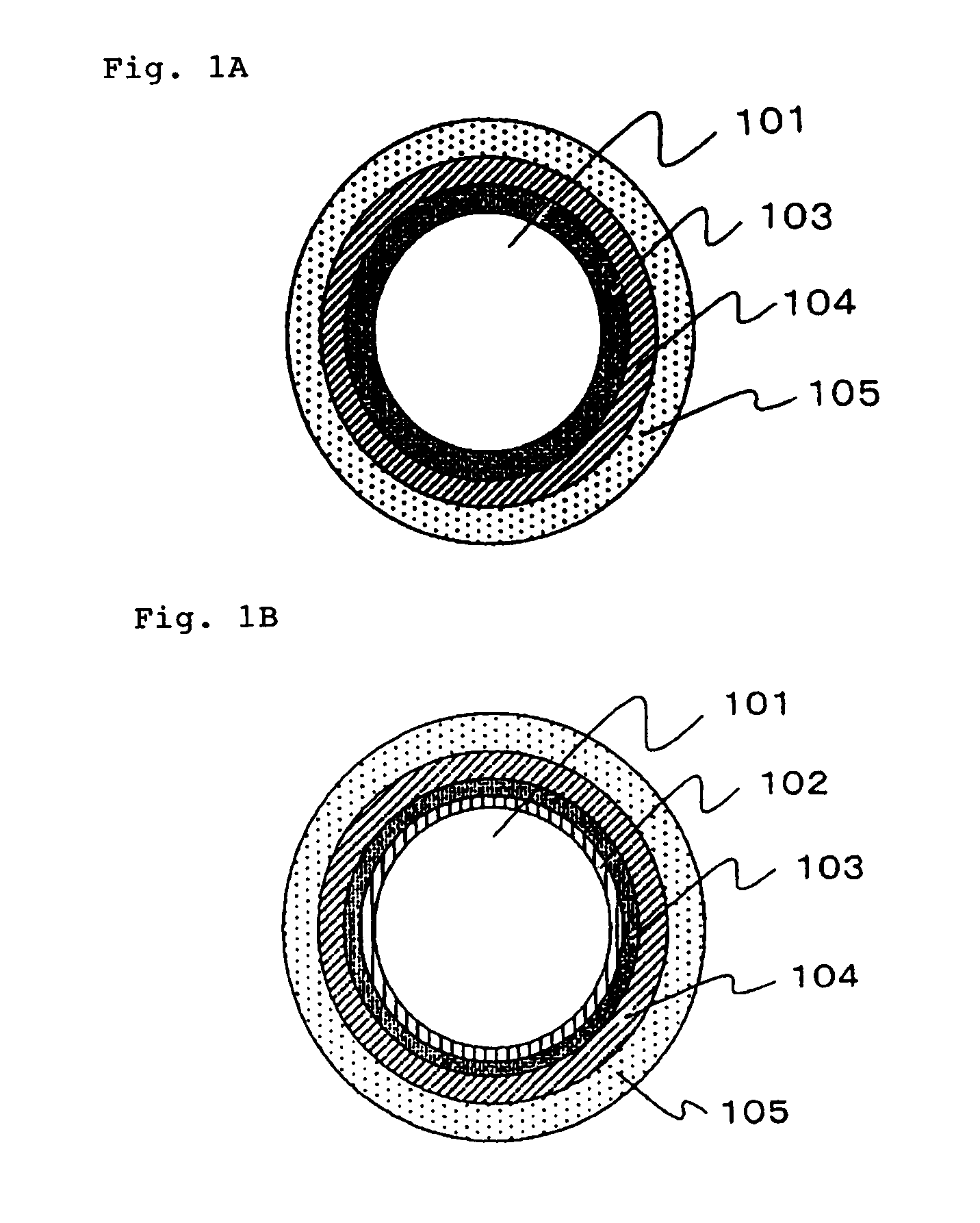
[0284]PMMA (refractive index: 1.492) was used as a core material, a copolymer (refractive index: 1.416 to 1.417) composed of 3FM / 17FM / MMA / MAA (composition ratio: 51 / 31 / 17 / 1 (% by mass)) was used as the 1st clad material, and a copolymer composed of VdF / TFE / HFP (composition ratio: 43 / 48 / 9 (% by mass), refractive index: 1.375, heat of crystal fusion (OH): 14 mJ / mg) was used as the 2nd clad material. These polymers were melted and supplied to a spinning head of 220° C. After composite spinning was performed by using a concentric composite nozzle, the polymer was stretched double in the fiber-axis direction in a hot-air heating furnace of 140° C. to obtain a bare POF of 1 mm in diameter having clads each having a thickness of 10 μm. The transmission loss of the resultant bare POF at a wavelength of 650 nm was as satisfactory as 130 dB / km.

[0285]The periphery of the bare POF prepared was coated with commercially available nylon 12 (trade name: DAIAMID-L1640 manufactured by Daicel-Evonik L...

examples 2a to 4a

[0290]As shown in Table 1, POF cables were obtained in the same manner as in Example 1A except that the thicknesses of the functional coating layer (C) and the functional coating layer (D) were changed. The resultant POF cables were satisfactory in any one of transmission performance, heat resistance, flexibility and flame retardancy, as shown in Table 2.

examples 5a to 7a

[0291]In Examples 5A to 7A, POF cables were obtained in the same manner as in Example 1 as shown in Table 1 except that the resin composition (II) for use in a functional coating layer (D) was changed to PA66(B) to PA66(D) shown in Table 3, respectively. The resultant POF cables were satisfactory in any one of transmission performance, heat resistance, flexibility and flame retardancy, as shown in Table 2. Slight difference was observed in heat resistance and bending-elastic modulus depending upon the difference in addition amounts of brominated polystyrene and antimony pentoxide serving as a flame retardant.


PUM

PropertyMeasurementUnit
crystalline melting pointaaaaaaaaaa
total thicknessaaaaaaaaaa

Abstract

A plastic optical fiber cable includes: a bare plastic optical fiber including a core formed of a polymer containing a methyl methacrylate unit, and a clad layer including a layer formed of a specific fluorine-containing olefin resin at least in the outermost layer; and a coating layer around the bare plastic optical fiber, the coating layer including a light-shielding coating layer formed of a specific nylon resin composition, a functional coating layer (C) and a functional coating layer (D) in this order, where one of the functional coating layer (C) and the functional coating layer (D) is formed of a resin composition (I) containing a polybutylene terephthalate resin as a major component or an ethylene-vinyl alcohol copolymer as a major component; the other is formed of a specific nylon resin composition (II); and a ratio of the thickness of the functional coating layer (C) to the thickness of the functional coating layer (D) is set to fall within a specific range.

Description

TECHNICAL FIELD[0001]The present invention relates to a plastic optical fiber cable having a coating layer of a layered structure, and particularly a highly flexible plastic optical fiber cable excellent in long-term heat resistance under a high-temperature environment, and a method of transmitting a signal by using the plastic optical fiber cable in combination with a visible-light emitting diode having an emission center wavelength in a range of 500 nm or more and 600 nm or less.BACKGROUND ART[0002]Conventionally, as an optical fiber, a quartz-based optical fiber of excellently transmitting light over a broad wavelength range has been put into practical use primarily for trunk lines. However, the quartz-based optical fiber is expensive and low in processability. Therefore, a plastic optical fiber (hereinafter simply referred to as a “POF”) being more inexpensive, light-weight and large in diameter and having favorable features in end-surface processability and easy-to-handle, has ...

Claims


Application Information

Patent Timeline
Patent Type & Authority Patents(United States)
IPC IPC(8): G02B6/036
CPCG02B1/046G02B1/048G02B6/02033C08L33/08C08L33/16C08L27/12G02B6/4436G02B6/02
Inventor TSUKAMOTO, YOSHIHIROKIMURA, TSUYOSHIFUJISHIGE, YASUSHIAKIHARA, RIEMATSUO, MITSUHIRO
Owner MITSUBISHI CHEM CORP
Why Eureka
Try Eureka