Perfluorinated membranes and improved electrolytes for redox cells and batteries

a technology of perfluorinated membranes and electrolytes, which is applied in the direction of sustainable manufacturing/processing, indirect fuel cells, cell components, etc., can solve the problems of capacity loss that cannot be corrected, unstable state of charge of positive and negative half-cell electrolytes, etc., and achieves low linear expansion, excellent performance, and reduced swelling. significant

Active Publication Date: 2013-09-24
NEWSOUTH INNOVATIONS PTY LTD
View PDF20 Cites 18 Cited by
  • Summary
  • Abstract
  • Description
  • Claims
  • Application Information

AI Technical Summary

Benefits of technology

[0007]In embodiments of the present invention, an improved perfluorinated membrane is described that has shown excellent performance in both the V / VRB and the V / BrRB redox flow batteries, thereby allowing the manufacture of a cell stack that can be used with either the Vanadium Sulphate or Vanadium Bromide electrolyte. Due to the different properties and fabrication method used, the behaviour of these membranes in the vanadium redox flow cells is vastly different from those of the corresponding Nafion or Gore Select perfluorinated membranes. Fabrication by dissolved resin solution casting has been found to be particularly advantageous since it results in a membrane with isotropic swelling and tensile strength properties and in particular the high level of swelling is considerably reduced compared to Nafion extruded membranes. The cast membranes show low linear expansion and insignificant swelling when wetted, can be allowed to dry out without any damage and can therefore be assembled in a dry or wet state. To maximise the performance of the cells, the improved perfluorinated membranes are typically pre-treated prior to use, this pre-treatment having the effect of reducing the resistance and therefore increasing the voltage efficiency during charge-discharge cycling. The membrane pre-treatment typically involves soaking the membrane in an aqueous solution for periods in excess of 20 minutes prior to use in the V / VRB or V / BrRB cell. The type of membrane treatment used has been found to be critical to the performance of the membrane in the V-VBR and V / BrRB and the inventors have found a number of excellent methods that give overall energy efficiencies of over 80% in both systems. Significantly, unlike all other membranes previously evaluated in the V / VRB or V / BrRB cells, this improved membrane shows good performance in both electrolytes, so that a redox cell stack for use with either electrolyte interchangeably can be manufactured, allowing significant manufacturing cost savings to be achieved.

Problems solved by technology

During operation of the V-VRB and V / BrRB, an imbalance in the state of charge of the positive and negative half-cell electrolytes can occur due to the air oxidation of the V(II) ions in the negative half-cell, or to the generation of hydrogen at the negative electrode during charging.
Both of these processes lead to capacity losses that cannot be corrected by simple electrolyte remixing, so a rebalance cell or process is needed to restore balance and therefore system capacity by restoring the correct approximately 1:1 ratio of V(II) to V(V) ions in the negative and positive half-cell solutions respectively of the V / VRB, or approximately 1:1 ratio of V(II) to Br3− ions in the negative and positive half-cell solutions respectively of the V / BrRB.

Method used


Image

  • Perfluorinated membranes and improved electrolytes for redox cells and batteries
  • Perfluorinated membranes and improved electrolytes for redox cells and batteries
  • Perfluorinated membranes and improved electrolytes for redox cells and batteries

Examples


example 1

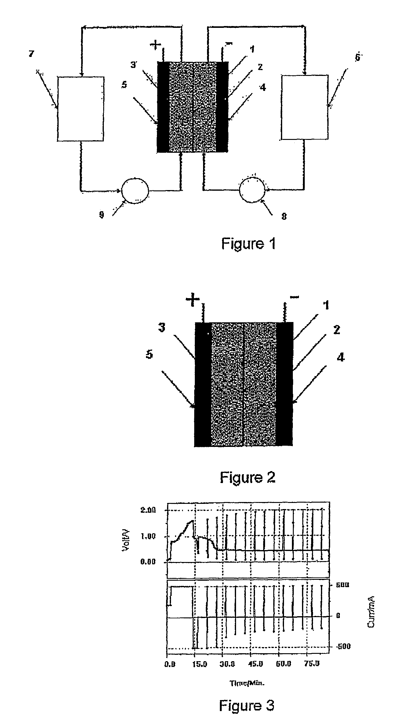
[0128]A piece of polysulphone anion exchange membrane was placed into a static vanadium bromide redox cell. FIG. 3 shows the voltage versus time curves obtained at a current of 500 mA and electrode area of 25 cm2. No discharge curves could be obtained

example 2

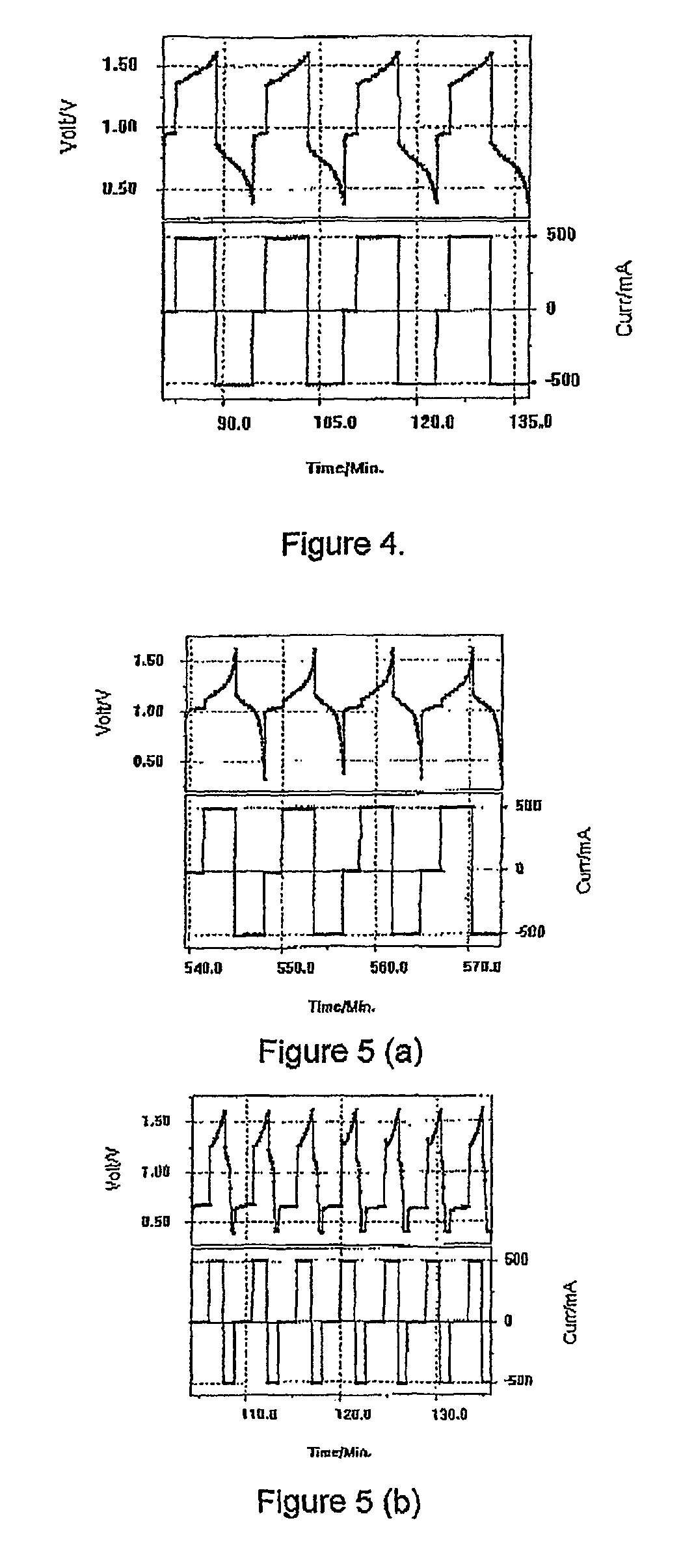
[0129]A piece of Nafion 112 membrane was placed into a Vanadium Bromide static cell comprising 2 M Vanadium in 6 M HBr plus 2 M HCl electrolyte and graphite felt electrodes of area 25 cm2. The cell was cycled at a current of 500 mA and typical charge-discharge curves are presented in FIG. 4. The Nafion initially showed a high voltage resistance and the following results were obtained:[0130]Voltage Efficiency—47%[0131]Columbic Efficiency—91%

[0132]After only a few hours of cycling however, the cell capacity dropped dramatically and further cycling could not be obtained.

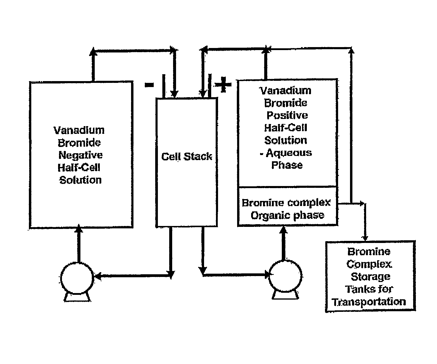
[0133]When the Nafion 112 membrane was placed in a flow cell containing 70 ml of the same electrolyte in each half-cell, the positive electrolyte began to cross over to the negative half-cell during the initial charge cycle and continued to transfer from the positive half-cell with further cycling, requiring regular manual transfer of solution back to the positive to maintain the electrolyte levels in the two solution r...

example 3

[0135]A perfluorinated cation exchange membrane prepared by casting from a solution of a resin with EW (Equivalent Weight)=1032 g resin / eq SO3−, so the ion exchange capacity=1 / EW=0.97 meq SO3− / g resin, was tested in a V / Br static cell. The 50 micron thick cast perfluorinated membrane had the following properties:[0136]Nominal Thickness: 2 mil or 50 microns[0137]Acid Capacity: 0.97 mmol / g[0138]Conductivity: 0.1 S / cm (25° C.)[0139]Water Uptake: 50% (100° C., 1 h)[0140]Linear Expansion: 1% (23° C., from 50% RH to water soaked)[0141]Tensile Strength: 37 MPa (50% RH, 23° C., Isotropy)[0142]Melting Point: 219° C.

[0143]The membrane was soaked in sulphuric acid at 50° C. for 1 hour and then placed in a static V / Br cell for cycling. The Vanadium Bromide (V / Br) static cell comprised 2 M Vanadium in 6 M HBr plus 1.5 M HCl electrolyte and graphite felt electrodes of area 25 cm2. The cell was cycled at a current of 500 mA. This showed good, stable results with the following efficiencies as illus...


PUM

PropertyMeasurementUnit
conductivityaaaaaaaaaa
melting pointaaaaaaaaaa

Abstract

The present invention describes an improved membrane for Redox Flow Batteries, in particular for Vanadium Redox Batteries and energy storage systems and applications employing the Vanadium Redox Cells and Batteries. Redox Flow Batteries involve the use of two redox couple electrolytes separated by an ion exchange membrane that is the most important cell component.

Description

RELATED APPLICATIONS[0001]This application is the U.S. National Phase of PCT / AU2006 / 000856 filed Jun. 19, 2006 and claims priority to Australian Provisional Patent Application Nos. 2005903230 filed Jun. 20, 2005 and 2005905012 filed Sep. 12, 2005, which are hereby incorporated herein by reference in their entirety.TECHNICAL FIELD[0002]The present invention describes an improved membrane for Redox Flow Batteries, in particular for Vanadium Redox Batteries and energy storage systems and applications employing the Vanadium Redox Cells and Batteries. Redox Flow Batteries involve the use of two redox couple electrolytes separated by an ion exchange membrane that is the most important cell component. A stable, low cost cation exchange membrane is needed for all redox flow cells that operate with an acidic electrolyte and the use of a highly oxidising positive half-cell redox couple in all redox flow cell systems means that the membrane must be stable to oxidising agents. Perfluorinated me...

Claims


Application Information

Patent Timeline
Patent Type & Authority Patents(United States)
IPC IPC(8): H01M4/13H01M4/58H01M2/16H01M10/0565
CPCB60L11/1879H01M8/1023H01M8/1067H01M8/1081H01M8/1088H01M8/109H01M8/20B60L2240/545H01M8/188H01M10/0565Y02E60/521Y02E60/528Y02T10/7005Y02T10/705Y02T90/16B60L50/64Y02E60/50Y02P70/50Y02T10/70Y02E60/10
Inventor KAZACOS, GEORGE CHRISTOPHERKAZACOS, NICHOLAS MICHAEL
Owner NEWSOUTH INNOVATIONS PTY LTD
Why Eureka
Try Eureka