
Image processing method, and image processor

a technology of image processing and image processor, applied in the field of image processing method and image processor, can solve the problems of insufficient visibility, deformation natural thickening of thermally reversible recording medium, etc., and achieve the effect of shortening the scanning direction of the scanning mirror and shortening the recording tim

Inactive Publication Date: 2014-01-14
RICOH KK
View PDF34 Cites 4 Cited by
  • Summary
  • Abstract
  • Description
  • Claims
  • Application Information

AI Technical Summary

Benefits of technology

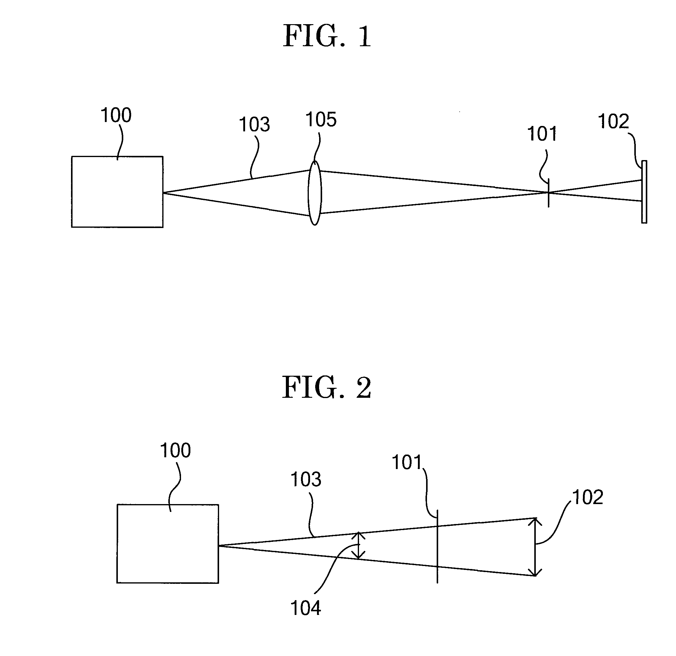
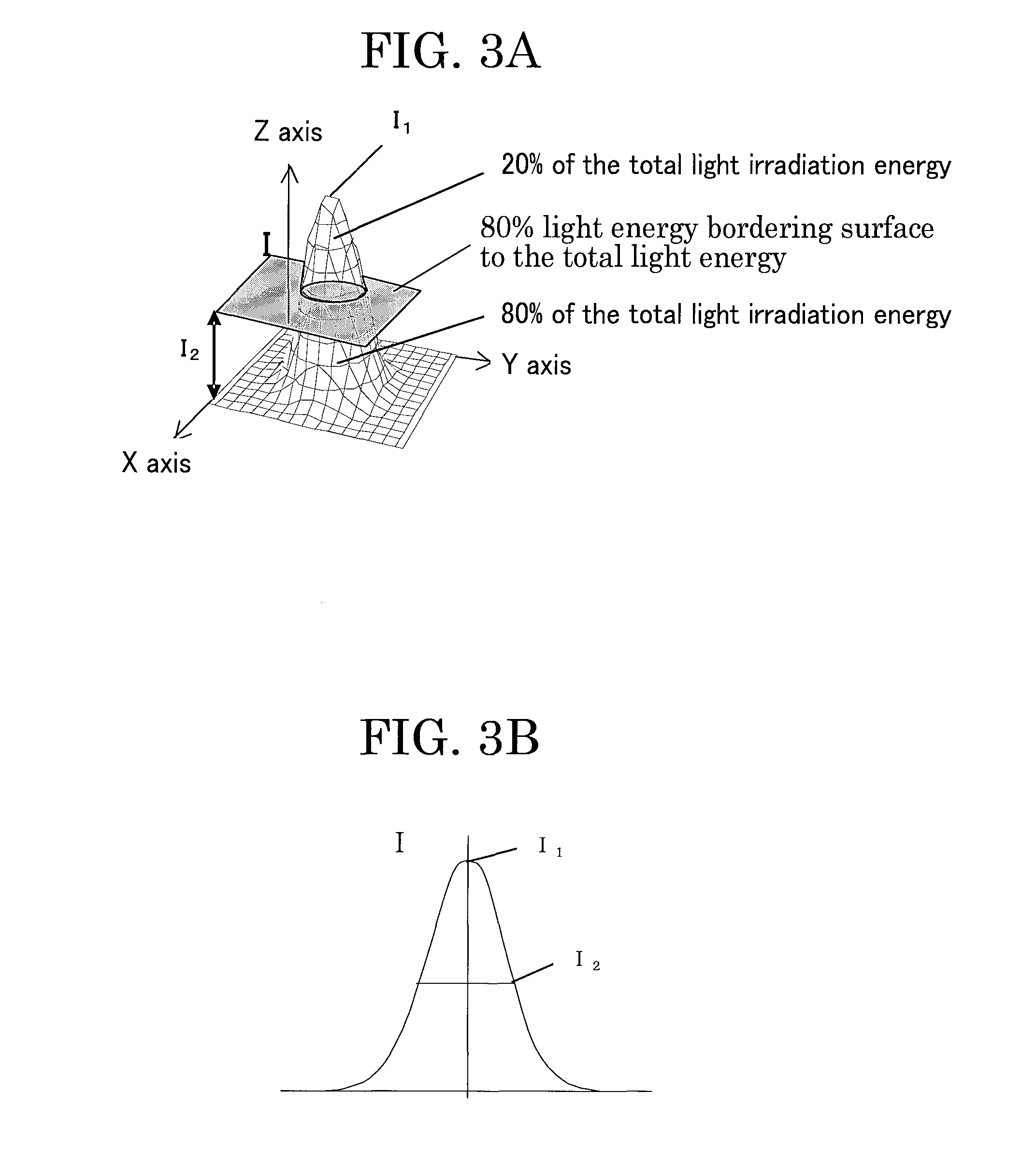
[0023]First, the present invention aims to provide an image processing method that allows for shortening a scanning direction of a scanning mirror and shortening recording time and erasing time than in recording and erasing an image at a position nearer than a focal position of a laser beam used or at the focal position and widening a recording area and an erasing area by placing a thermally reversible recording medium at a position farther than the focal position of the laser beam and performing any one of image recording and image erasing, and also to provide an image processor that can be suitably used in the image processing method.
[0024]Secondarily, the present invention aims to provide an image processing method that enables preventing an excessive amount of energy from being applied to the entire image lines including start points, end points, folding points and straight lines constituting an image and enables preventing deterioration of a thermally reversible recording medium by reducing damage attributable to repeated recording and erasing of each image, and also to provide an image processor that can be preferably used in the image processing method.
[0025]Thirdly, the present invention aims to provide an image processing method that enables an image to be uniformly recorded and erased at high-image density for the entire image lines including start points, end points, folding points and straight lines constituting an image and enables preventing deterioration of a thermally reversible recording medium by reducing damage attributable to repeated recording and erasing of each image, and to also provide an image processor that can be preferably used in the image processing method.

Problems solved by technology

However, when a thermally reversible recording medium incorporates an RF-ID tag as described in Japanese Patent Application Laid-Open (JP-A) Nos. 2004-265247 and 2004-265249, the thickness of the thermally reversible recording medium is naturally thickened and the flexibility thereof is degraded.
Further, when there are convexoconcave or irregularities on the surface of a thermally reversible recording medium, it becomes difficult to record and erase an image using a thermal head or the like.
Therefore, the visibility may be insufficient.
Further, when the image is erased using a laser beam, image displacement may occur to cause erasing residue due to the small spot diameter of the laser beam at the focal position.
There is a problem that when a laser beam is extensively scanned so as not to cause such erasing residue, it takes a long time to erase an image.
However, these techniques require mounting a spot diameter changing unit to a laser recording device.
Therefore, the laser recording device is naturally increased in size, resulting in a high cost.
Therefore, when each image is recorded and erased at that position, the scanning distance of a scanning mirror is longer than the scanning distance when each image is recorded and erased at the focal point, and it takes longer time to record and erase each image.
Further, when a thermally reversible recording medium is located so as to be closer than the focal position, there is a problem that recorded regions and erased regions become narrower.
Because of repeated recording at the overlap portion on a thermally reversible recording medium, an excessive amount of energy is applied to the overlap portion, and it may sometimes damage the thermally reversible recording medium.
Further, at a start point of an image line, the irradiation power of the laser beam may become unstable because of incapability of controlling the irradiation power, and an excessive irradiation power may be sometimes applied to the thermally reversible recording medium (overshooting).
Further, when an image line is folded at an overlap portion, it is difficult to instantaneously change a mirror angle by means of mortar actuation, and thus the scanning speed of the laser beam is lowered, and an excessive amount of energy is applied to the overlap portion.
Therefore, there is a problem that a thermally reversible recording medium is damaged by repeatedly recording and erasing an image.
For this reason, similarly to the case of using a scanning mirror, an excessive amount of energy is applied to start points and end points of a recorded image, and there may be cases where the thermally reversible recording medium is damaged.
However, at a start point of an image line, the irradiation power of the laser beam may become unstable because of incapability of controlling the irradiation power, and an excessive irradiation power may be sometimes applied to the thermally reversible recording medium (overshooting).
For this reason, the scanning speed of the scanning mirror is decelerated at a recording start point (start point), a recording end point (end point) and a folded point where the rotational direction of the scanning mirror is changed, and an excessive amount of energy is applied to these points, and there may be cases where the thermally reversible recording medium is damaged due to repeated recording and erasing.
For this reason, similarly to the case of using a scanning mirror, an excessive amount of energy is applied to a start point and an end point of a recorded image, and there may be cases where the thermally reversible recording medium is damaged.
On these points, even when an excessive amount of energy is applied to a conventional non-reversible heat-sensitive recording medium, this does not become a major problem, however, on a thermally reversible recording medium where each image is repeatedly recorded and erased, there is a large problem that an excessive amount of energy is applied to the same portions to cause damage to the recording medium, and each image cannot be uniformly recorded at high-image density and cannot be uniformly erased due to accumulation of damage.
However, when a uniform image is recorded at high-density and erased repeatedly by using a highly energized laser, not only a start point, an end point and a folding portion of an image line but also the center portion of a straight line are excessively heated, deformed sites and air bubbles are observed on the surface of the thermally reversible recording medium, and materials themselves each exhibiting color developing-color erasing properties are thermally decomposed, and these materials cannot exert their sufficient ability.
As a result, on the entire image lines including start points, end points, folding portions and straight lines constituting an image, it is impossible to uniformly record the image with high-image density and is impossible to uniformly erase the image on a sufficient level, and as an image processing method that causes less deterioration of a thermally reversible recording medium even when the image is repeatedly recorded and erased, there is much to be desired, and further improvements and developments are still desired.

Method used


Image

  • Image processing method, and image processor
  • Image processing method, and image processor
  • Image processing method, and image processor

Examples


production example 1

Preparation of Thermally Reversible Recording Medium

[0442]A thermally reversible recording medium capable of reversibly changing in color tone between a transparent state and a color developed state depending on temperature was prepared as follows.

—Substrate—

[0443]As a substrate, a white turbid polyester film of 125 μm in thickness (TETRON FILM U2L98W, manufactured by TEIJIN DUPONT FILMS JAPAN LTD.) was used.

—Under Layer—

[0444]To 40 parts by mass of water, 30 parts by mass of a styrene-butadiene copolymer (PA-9159, manufactured by Nippon A & L Inc.), 12 parts by mass of a polyvinyl alcohol resin (POVAL PVA103, manufactured by KURARAY Co., Ltd.), and 20 parts by mass of a hollow particle (MICROSPHERE-300, manufactured by Matsumoto Yushi-Seiyaku Co., Ltd.) were added to prepare an under layer coating solution.

[0445]Next, the obtained under layer coating solution was applied over a surface of the substrate using a wire bar, and the applied coating solution was heated at 80° C. for 2 mi...

production example 2

Preparation of Thermally Reversible Recording Medium

[0457]A thermally reversible recording medium capable of reversibly changing in color tone between a transparent state and a color developed state depending on temperature was prepared as follows.

—Substrate—

[0458]As a substrate, a transparent PET film of 175 μm in thickness (LUMILAR 175-T12, manufactured by Toray Industries, Inc.) was used.

—Reversible Thermosensitive Recording Layer (Recording Layer)—

[0459]In a resin solution in which 26 parts by mass of vinyl chloride copolymer (M110, manufactured by ZEON CORPORATION) had been dissolved in 210 parts by mass of methylethylketone, and 3 parts by mass of an organic low-molecular material represented by the following Structural Formula (5) and 7 parts by mass of dococyl behenate were added. A ceramic bead having a diameter of 2 mm was put in a glass bottle, and the prepared solution was poured thereto. The solution was dispersed using a paint shaker (manufactured by Asada Tekko Co., L...

production example 3

Preparation of Thermally Reversible Recording Medium

[0464]A thermally reversible recording medium of Production Example 3 was prepared in the same manner as in Production Example 1 except that 0.03 parts by mass of a photothermal conversion material (EXCOLOR IR-14, manufactured by NIPPON SHOKUBAI CO., LTD.) was added in the preparation of the thermally reversible recording medium.


PUM

PropertyMeasurementUnit
speedaaaaaaaaaa
speedaaaaaaaaaa
diameteraaaaaaaaaa

Abstract

The present invention provides an image processing method which includes any one of recording an image on a thermally reversible recording medium that can reversibly change any one of its transparency and color tone depending on temperature by irradiating and heating the thermally reversible recording medium with a laser beam, and erasing the image recorded on the thermally reversible recording medium by heating the thermally reversible recording medium, wherein in any one of the image recording and the image erasing, the thermally reversible recording medium is located at a position farther than a focal position of the laser beam, and at least any one of the image recording and the image erasing is performed.

Description

BACKGROUND OF THE INVENTION[0001]1. Field of the Invention[0002]The present invention relates to an image processing method and an image processor that can be suitably used in the image processing method.[0003]2. Description of the Related Art[0004]Until now, an image have been recorded and erased on a thermally reversible recording medium (hereinafter, may be referred to as “recording medium” or “medium” merely) by a contact method in which the thermally reversible recording medium is heated by making contact with a heat source. For the heat source, in the case of image recording, a thermal head is generally used, and in the case of image erasing, a heat roller, a ceramic heater or the like is generally used.[0005]Such a contact type recording method has advantages in that when a thermally reversible recording medium is composed of a flexible material such as film and paper, an image can be uniformly recorded and erased by evenly pressing a heat source against the thermally reversi...

Claims


Application Information

Patent Timeline
Patent Type & Authority Patents(United States)
IPC IPC(8): B41M5/26
CPCG02B5/22B41M5/305B41M5/26B41J2/4753
Inventor KAWAHARA, SHINYAHOTTA, YOSHIHIKOISHIMI, TOMOMI
Owner RICOH KK
Learn More