Stack structure for laminated solid oxide fuel cell, laminated solid oxide fuel cell and manufacturing method

a technology of solid oxide fuel cell and stack structure, which is applied in the manufacture of cell components, final product manufacturing, electrochemical generators, etc., can solve the problems of more difficult construction of stack structure, reduce the internal resistance of solid electrolyte, reduce the thickness of solid electrolyte, and improve power generation characteristics

Inactive Publication Date: 2014-02-25
FCO +1
View PDF17 Cites 27 Cited by
  • Summary
  • Abstract
  • Description
  • Claims
  • Application Information

AI Technical Summary

Benefits of technology

[0007]In an electrode-supported cell, the mechanical strength is provided by the electrodes, which are porous and must thus be relatively thick in order to ensure the necessary mechanical strength. Although reducing the thickness of the solid electrolyte reduces the internal resistance of the solid electrolyte itself, moreover, the internal resistance of the electrodes is increased concomitantly, and so the desired improvement in power generating characteristics has yet to be achieved.
[0009]It is therefore an object of the present teachings to provide a laminated SOFC having a stack structure capable of ensuring the mechanical strength of the SOFC as a whole without relying on the mechanical strength of the single cells. It is another object of the present teachings to provide a laminated SOFC having a stack structure capable of effectively reducing internal resistance to provide good power generating characteristics. It is another object of the present teachings to provide a laminated SOFC having a stack structure capable of improving thermal shock resistance. It is still another object of the present teachings to provide a laminated SOFC having a stack structure that can be easily stacked. It is yet another object of the present teachings to provide a manufacturing method for manufacturing such a laminated SOFC.

Problems solved by technology

This is because providing the single cell support with enhanced mechanical strength actually makes it more difficult to construct the stack structure.

Method used


Image

  • Stack structure for laminated solid oxide fuel cell, laminated solid oxide fuel cell and manufacturing method
  • Stack structure for laminated solid oxide fuel cell, laminated solid oxide fuel cell and manufacturing method
  • Stack structure for laminated solid oxide fuel cell, laminated solid oxide fuel cell and manufacturing method

Examples


example 1

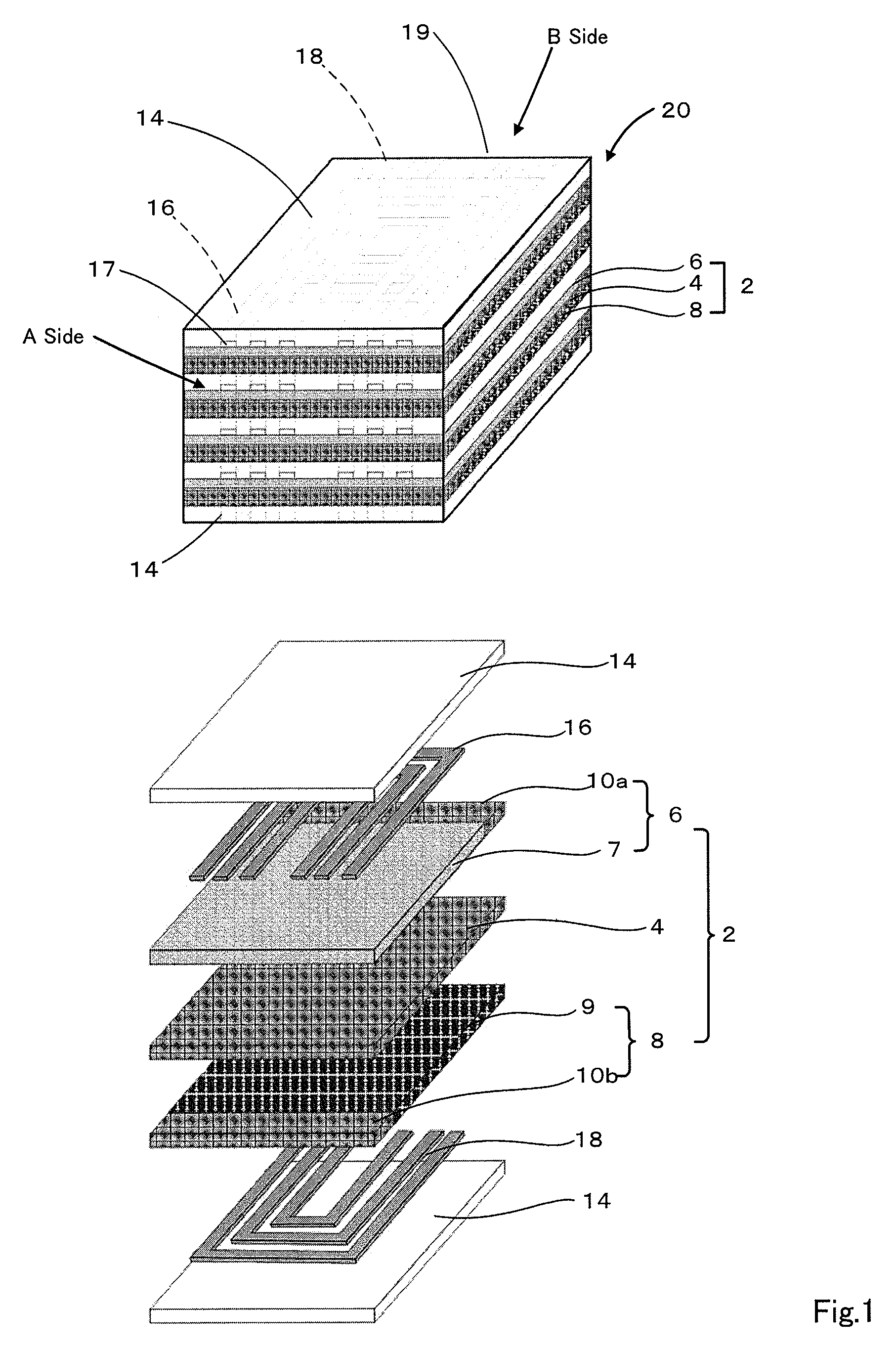
[0089]In this example, Ni / 8YSZ cermet (Ni:8YSZ=80:20 (mole ratio)) was used for the fuel electrode, La0.8Sr0.2MnO3 (LSM) for the air electrode, 8YSZ for the electrolyte, and La0.79Ca0.06Sr0.15CrOx (LCaSCr) for the separator. Slurries of each were prepared, and the separator sheet and solid electrolyte sheet were prepared by tape casting as green sheets 20 μm to 80 μm thick. For the air electrode sheet, a 20 μm-thick green sheet was prepared having an air electrode material region with a seal material region consisting of separator material at one end. For the fuel electrode sheet, a 20 μm-thick green sheet was prepared having a fuel electrode region with a seal material region consisting of separator material at one end. The slurry concentrations were adjusted for each sheet to obtain uniform shrinkage of the green sheets during heat treatment.

[0090]These sheets were laminated as shown in FIG. 6, and fired in air at 1400° C. The resulting structure was integrated without warpage, re...

example 2

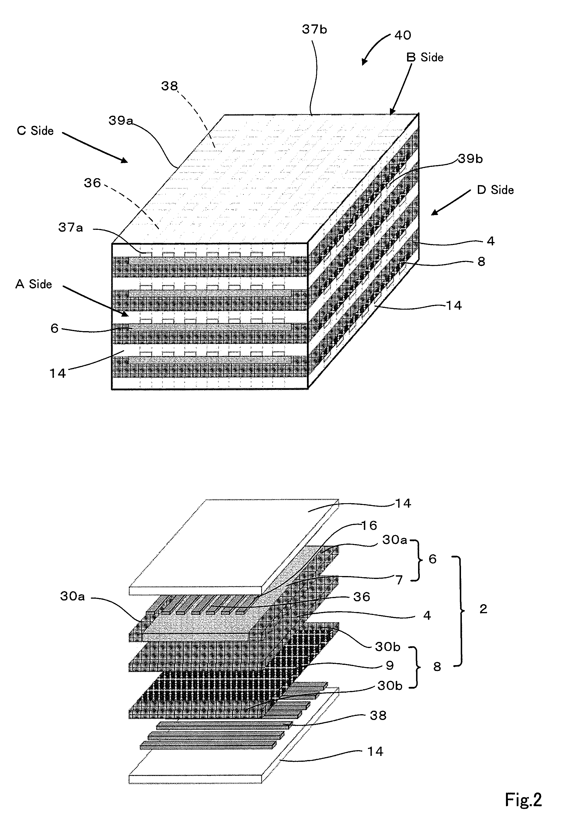
[0093]In this example, carbon paste was screen printed when laminating the separator sheet to the air electrode sheet and the separator sheet to the fuel electrode sheet in Example 1, and firing was performed as in Example 1. The resulting structure was shown to have spaces formed in the regions where carbon paste was applied, while still maintaining overall integrity as a structure. This shows that fine gas channels can be formed using an evaporative material.

example 3

[0094]In this example, LaCaSCr powder was compounded with 3YSZ (3 mole % yttrium-stabilized zirconia) in amounts of 1%, 2%, 3%, 4%, 5% and 7% of the mass of the oxide powder and roughly 10 mass % calcium nitrate in addition to these oxide powders, and mixed well in a mortar. This mixed powder was molded in a uniaxial press (1300 kgf / cm2, 5 minutes), and fired for 5 hours in atmosphere at 1300° C. A comparative example was also prepared by the same operations but with no 3YSZ added (sample with 0 mass % calcium nitrate-containing 3YSZ).

[0095]The volume and weight of the resulting sintered body were measured, and the density calculated. The results are shown in FIG. 8. FIG. 9 shows the results of scanning electron microscope (SEM) observation of cross-sections of the resulting sintered bodies (0 mass % and 1 mass % samples).

[0096]As shown in FIG. 8, the density of the lanthanum-calcium-strontium-chromium oxide, which was 5.3 g / cm3 without added 3YSZ, rose to 6% with 1 mass % 3YSZ adde...


PUM

PropertyMeasurementUnit
thicknessesaaaaaaaaaa
thicknessaaaaaaaaaa

Abstract

A stack structure for a solid oxide fuel cell includes a plurality of stacked single cells, each having a fuel electrode layer including a fuel electrode and an air electrode layer including an air electrode, the fuel electrode layer and the air electrode layer being arranged opposite each other on either side of a solid electrolyte, separators arranged between the stacked single cells to separate the single cells, and non-porous seal parts located within the fuel electrode layer and the air electrode layer, are equivalent to either the separators or the solid electrolyte at least in terms of thermal expansion and contraction characteristics, and are integrated with an edge of the fuel electrode or an edge of the air electrode, and also with the adjacent separator and the adjacent solid electrolyte.

Description

TECHNICAL FIELD[0001]The present teachings relates to a stack structure for a laminated solid oxide fuel cell, and to a laminated solid oxide fuel cell and a method of manufacturing the same.BACKGROUND ART[0002]In a solid oxide fuel cell (sometimes abbreviated below as SOFC), a unit consisting of a fuel electrode, a solid electrolyte and an air electrode is called a single cell, and a plurality of these units is stacked to achieve a serial connection and construct a power generating system. Tens to hundreds of single cells must be stacked to obtain adequate power output, and the single cells must be mechanically strong enough to provide stable, long-term power generation in such a highly stacked state. For this reason, it is common to use electrolyte-supported cells comprising a solid electrolyte hundreds of microns thick with a fuel electrode and air electrode tens of microns thick printed on either side of the solid electrolyte.[0003]In order to improve a power generating characte...

Claims


Application Information

Patent Timeline
Patent Type & Authority Patents(United States)
IPC IPC(8): H01M8/00H01M8/24H01M8/02
CPCH01M8/2485Y02E60/50H01M8/0282H01M8/2425H01M2008/1293H01M8/0286Y02E60/525H01M8/0276Y02P70/50H01M8/2432H01M8/2404H01M8/0263
Inventor SUDA, SEIICHIJONO, KAORIHASHIMOTO, FUMIOHASHIMOTO, TAKAYUKI
Owner FCO
Why Eureka
Try Eureka