Solar energy utilization device and method for manufacturing the same

a solar energy and utilization device technology, applied in silicon compounds, instruments, non-linear optics, etc., can solve the problems of not achieving substantial reduction of surface reflection of incident light, insufficient anti-fouling and water-repellency properties of solar cells and solar water heaters, and insufficient anti-fouling properties of solar water heaters. achieve the effect of improving weather resistance, improving mechanical strength of the foregoing water-and-oil-shedding coating, and short tim

Inactive Publication Date: 2014-02-25
EMPIRE TECH DEV LLC
View PDF31 Cites 0 Cited by
  • Summary
  • Abstract
  • Description
  • Claims
  • Application Information

AI Technical Summary

Benefits of technology

[0008]Regarding a solar energy utilization device, such as solar cells and solar water heaters that require high durability, high water-repellency, and water-and-oil-shedding antifouling properties, the present invention aims toward providing a solar energy utilization device and the method for manufacturing the same, which will improve the power generation efficiency of solar cells and the heat collection efficiency of solar water heaters or glasshouses and which can prevent deterioration over time by dirt by improving wear resistance, high water-repellency, and antifouling properties, as well as the effect of reducing the surface reflection of the incident light.
[0045]As described above, regarding a solar energy utilization device, such as solar cells and solar water heaters that require high durability, high water-repellency, and water-and-oil-shedding antifouling properties, the present invention has the effect of improving the power generation efficiency of solar cells and the heat collection efficiency of solar water heaters, as well as preventing deterioration over time by dirt, at the same time, by reducing the surface reflection of the incident light and improving the wear resistance, high water-repellency, and antifouling property; thus, providing solar cells that can maintain power generation efficiency for a long period of time and solar water heaters that can maintain heat collection efficiency for a long period of time.

Problems solved by technology

Since conventional monomolecular films use the chemical bond between the adsorption agent and the surface of the base material, they have a certain wear resistance and water-and-oil-shedding antifouling properties; however, there was a sufficiency problem that the weather resistance, water-repellency, and antifouling properties were not sufficient for an antifouling coating of solar cells and solar water heaters.
In addition, since the coating was extremely thin, we could not expect a substantial reducing effect on the surface reflection of the incident light.

Method used


Image

  • Solar energy utilization device and method for manufacturing the same
  • Solar energy utilization device and method for manufacturing the same
  • Solar energy utilization device and method for manufacturing the same

Examples


example 1

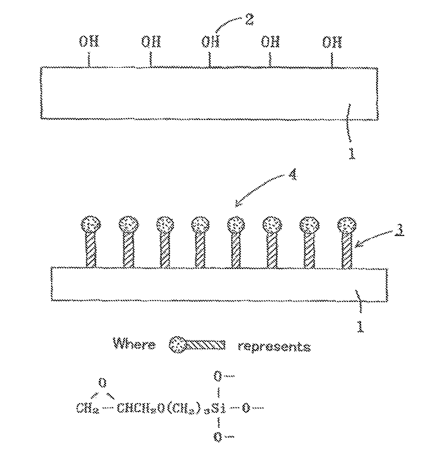
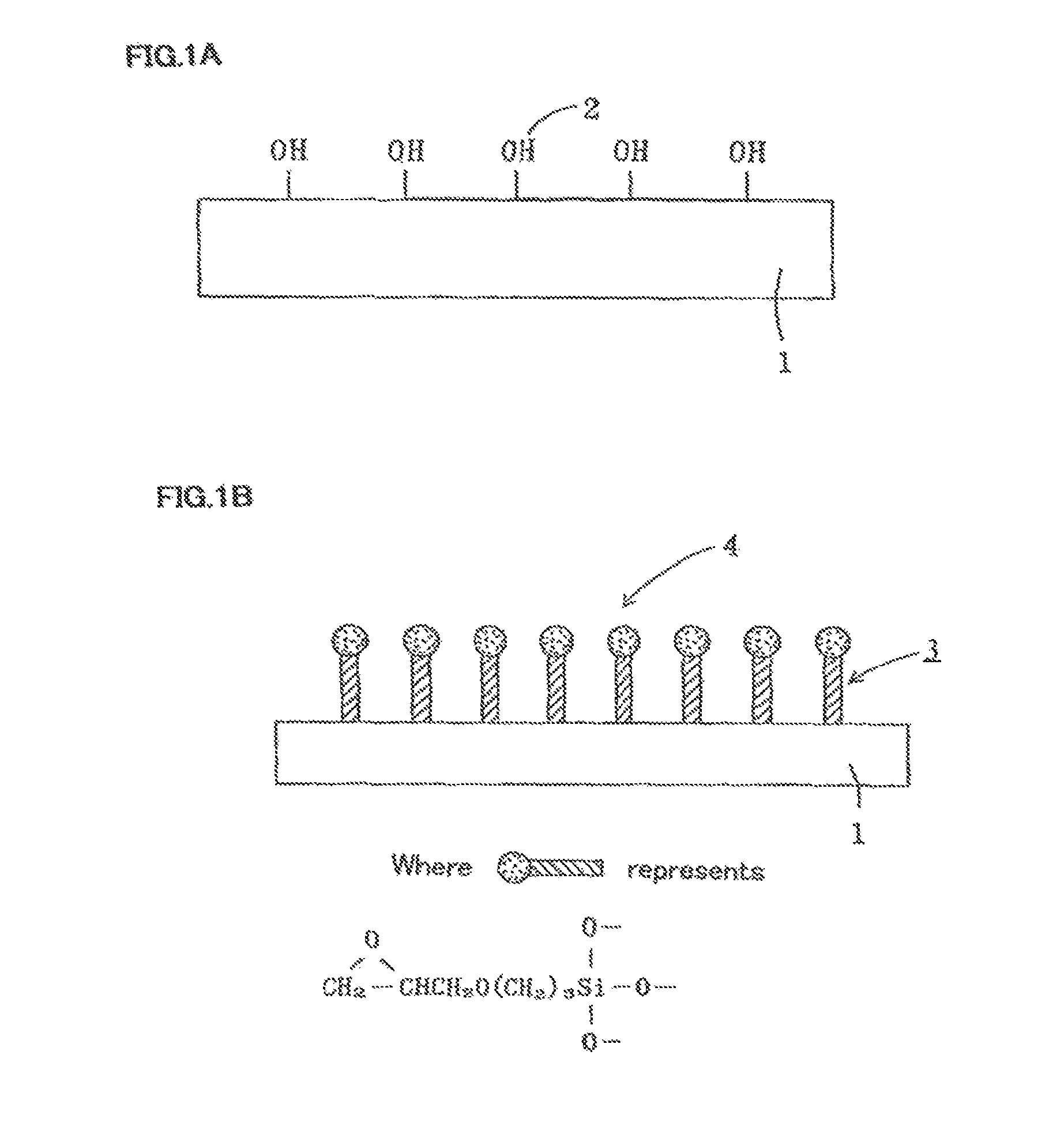
[0055]First, as the incident light side of the transparent base material of solar cells, a glass-made transparent base material 1 was prepared, cleaned, and dried thoroughly. Next, the second film compound containing the reactive second functional group (e.g., epoxy group) at the functional site and an alkoxysilyl group (as an example of the second binding group) at the other end (for example, the film compound shown in the following chemical formula [Formula C1]) was measured at 99 w / t %, and as a silanol condensation catalyst (for example, dibutyltin diacetylacetonate), was measured at 1 w / t %, respectively, and these were dissolved into a silicone solvent (e.g., hexamethyldisiloxane solvent) to prepare a chemical adsorption liquid so that it had a total concentration of about 1 w / t % (preferably, the concentration of the film compound is between approximately 0.5% to 3%).

[0056]

[0057]This adsorption liquid was applied to the surface of the foregoing transparent base material 1 and...

example 2

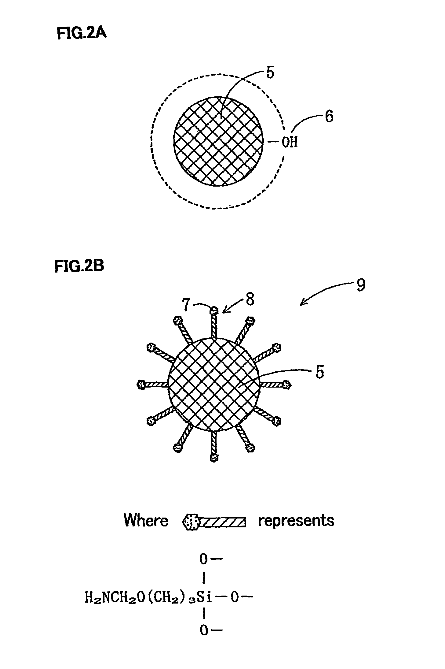
[0083]However, in Example 1, if the adsorption liquid containing CF3(CF2)7(CH2)2SiCl3 was applied to the surface of the transparent base material for reaction in the same manner, except for not performing a sintering process, since the fine alumina particles 5 on the surface of the transparent base material 4 covalently bound only in one layer via two monomolecular films were covered by many amino groups (surface groups) 7 (FIG. 3A), it causes a de-hydrochloric acid reaction between the chlorosilyl group (SiCl group) of the foregoing chemical adsorption agent and the amino group (—NH2) of the foregoing alumina fine particles to generate a bond as shown in the following formula [Formula C7] throughout the surface. Later, it was cleaned with a chlorofluorocarbon solvent, so that the plane on the incident light side was covered by a water-and-oil-shedding antifouling monomolecular film 16A (an example of water-and-oil-shedding coating) comprising the foregoing water-and-oil-shedding co...

example 3

[0087]In the same way as Examples 1 and 2, a transparent base material 10A, wherein the fine alumina particles were directly bound and fixed only in one layer to the surface of the transparent base material of the solar cell by sintering, or a transparent base material 10, wherein the fine alumina particles were bound and fixed only in one layer via a covalent bond formed between the film compounds, was manufactured. Then, after solar cell layers 12 through 15, or 12A through 15a were manufactured at the back, a water-and-oil-shedding compound containing a fluorocarbon group (—CF3) at one end and an alkoxysilyl group at the other end (for example, the water-and-oil-shedding compound represented by CF3(CF2)7(CH2)2Si(OCH3)3) was measured at 99 w / t %, and as a silanol condensation catalyst (for example, dibutyltin diacetylacetonate) was measured at 1 w / t %, respectively, and these were dissolved into a silicone solvent (e.g., hexamethyldisiloxane solvent) to prepare a chemical adsorpti...


PUM

PropertyMeasurementUnit
sizeaaaaaaaaaa
melting temperatureaaaaaaaaaa
thicknessaaaaaaaaaa

Abstract

A solar energy utilization device wherein the surface of the incident light side of the transparent base material 1 is covered by water-and-oil-shedding transparent fine particles 5 being bound and fixed to the surface. A method for manufacturing a solar energy utilization device comprising process A of manufacturing reactive transparent fine particles 9 with the first functional group at one end; process B of manufacturing reactive transparent base material 4 with the second functional group at one end forming a covalent bond with the first functional group; process C of manufacturing transparent base material 10 by reacting the reactive transparent fine particles 9 with the reactive transparent base material 4 for binding and fixing the reactive transparent fine particles 9 to the surface; and process D of forming water-and-oil-shedding coating 16 on the surface of the transparent fine particles 5 being bound and fixed to the surface of the transparent base material 10.

Description

BACKGROUND OF THE INVENTION[0001]1. Field of the Invention[0002]The present invention is related to a solar energy utilization device, such as a solar cell, a solar water heater, or a glasshouse, and the method for manufacturing the same, wherein the device has durability, high water-repellency (water-sliding property), and an effect of reducing a surface reflection of incident light, including water-and-oil-shedding transparent fine particles formed on an incident light side of a surface of a transparent base material.[0003]2. Description of Related Art[0004]Generally, it is well known that the power generation efficiency of solar cells that are installed outside and the heat collection efficiency of solar water heaters or glasshouses deteriorate over time due to the build-up of dirt from rain and dust in the air.[0005]It is also well known that a chemical adsorption liquid including a fluorocarbon chlorosilane-based adsorption agent and non-aqueous organic solvent can be used to f...

Claims


Application Information

Patent Timeline
Patent Type & Authority Patents(United States)
IPC IPC(8): H01L31/00
CPCH01L31/068Y02E10/52C09D5/1693H01L31/0236C03C17/42Y02E10/547H01L31/03762C03C2217/76H01L31/02168Y02E10/548C03C2217/42
Inventor OGAWA, KAZUFUMI
Owner EMPIRE TECH DEV LLC
Why Eureka
Try Eureka