Method and system for determining energy content and detecting contaminants in a fluid stream

a technology of energy content and fluid stream, applied in the field of real-time, in-situ monitoring of fluids, can solve the problems of sulfide component being extremely toxic and irritating gas, eye irritation, headaches at low concentration, unconsciousness or death, etc., and achieves high resolution and power level.

Active Publication Date: 2014-04-01
JP3 MEASUREMENT
View PDF18 Cites 50 Cited by
  • Summary
  • Abstract
  • Description
  • Claims
  • Application Information

AI Technical Summary

Problems solved by technology

The hydrogen sulfide component is an extremely toxic and irritating gas, causing eye irritation, dizziness, coughing, and headaches at low concentrations and unconsciousness or death at higher concentration if released into the local environment.
In addition to its adverse human health effects, the presence of hydrogen sulfide in natural gas can cause sulfide stress cracking and hydrogen-induced cracking to the lines through which the gas is transmitted.
Also, the presence of liquid condensate in the gas stream cannot be measured by a gas chromatography system, but can be detected by an NIR spectrometer.
Unfortunately, determining the amount of hydrogen sulfide in situ in a natural gas stream under pressure is extremely difficult.
This is complicated by the fact that there are species of hydrocarbons in natural gas whose absorption frequencies may interfere with hydrogen sulfide's absorption frequency, most notably methane (CH4) and carbon monoxide (CO), but in some cases also some of the larger alkane molecules such as propane (C3H8).
Finally, because absorption lines broaden with increasing pressure and temperature, hydrogen sulfide analysis with tunable diode lasers that are only capable of creating a very narrow range of NIR excitation frequency and focus on a single absorption peak is restricted to a certain maximum pressure and process temperature.

Method used


Image

  • Method and system for determining energy content and detecting contaminants in a fluid stream
  • Method and system for determining energy content and detecting contaminants in a fluid stream
  • Method and system for determining energy content and detecting contaminants in a fluid stream

Examples


Embodiment Construction

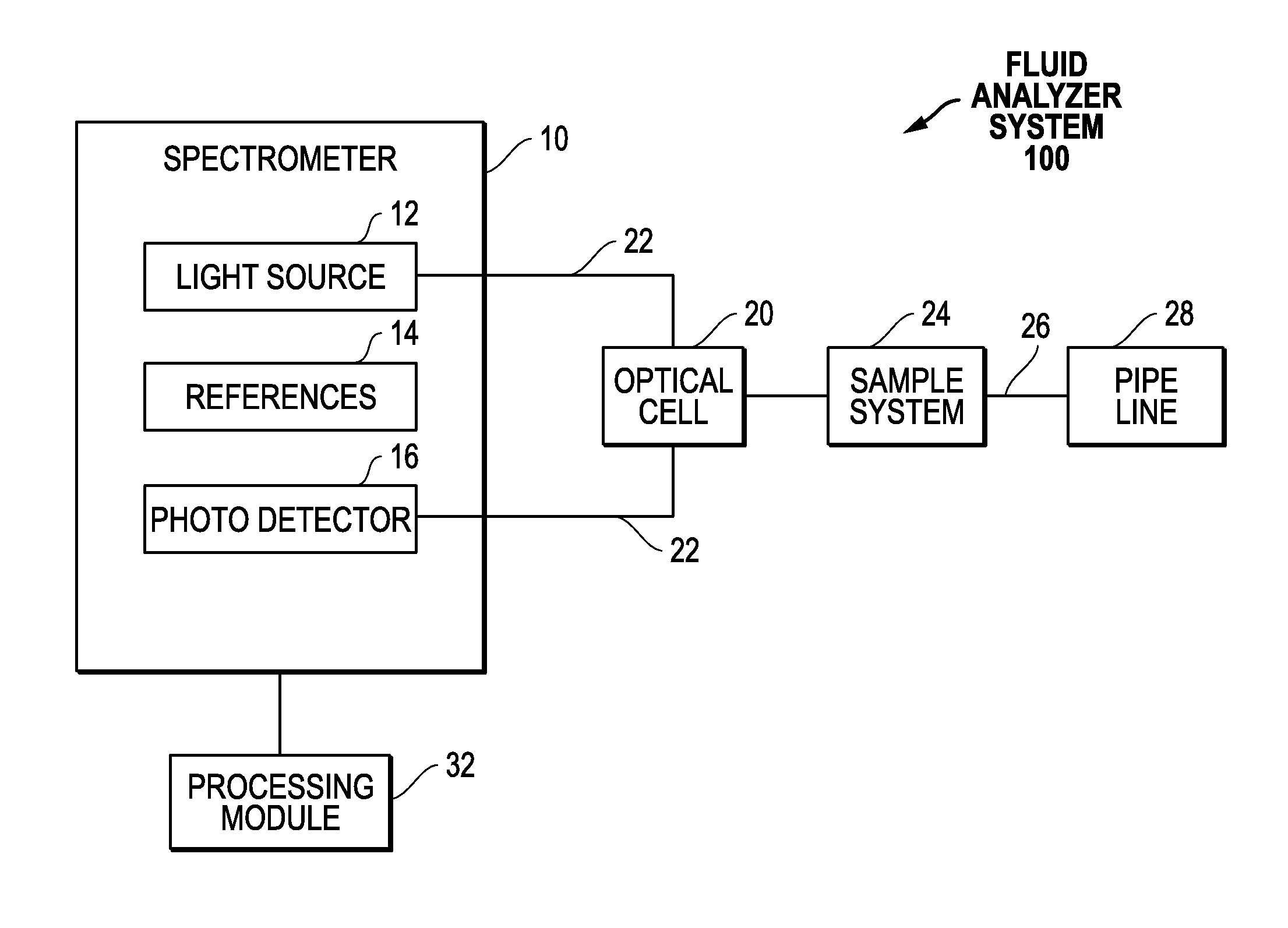
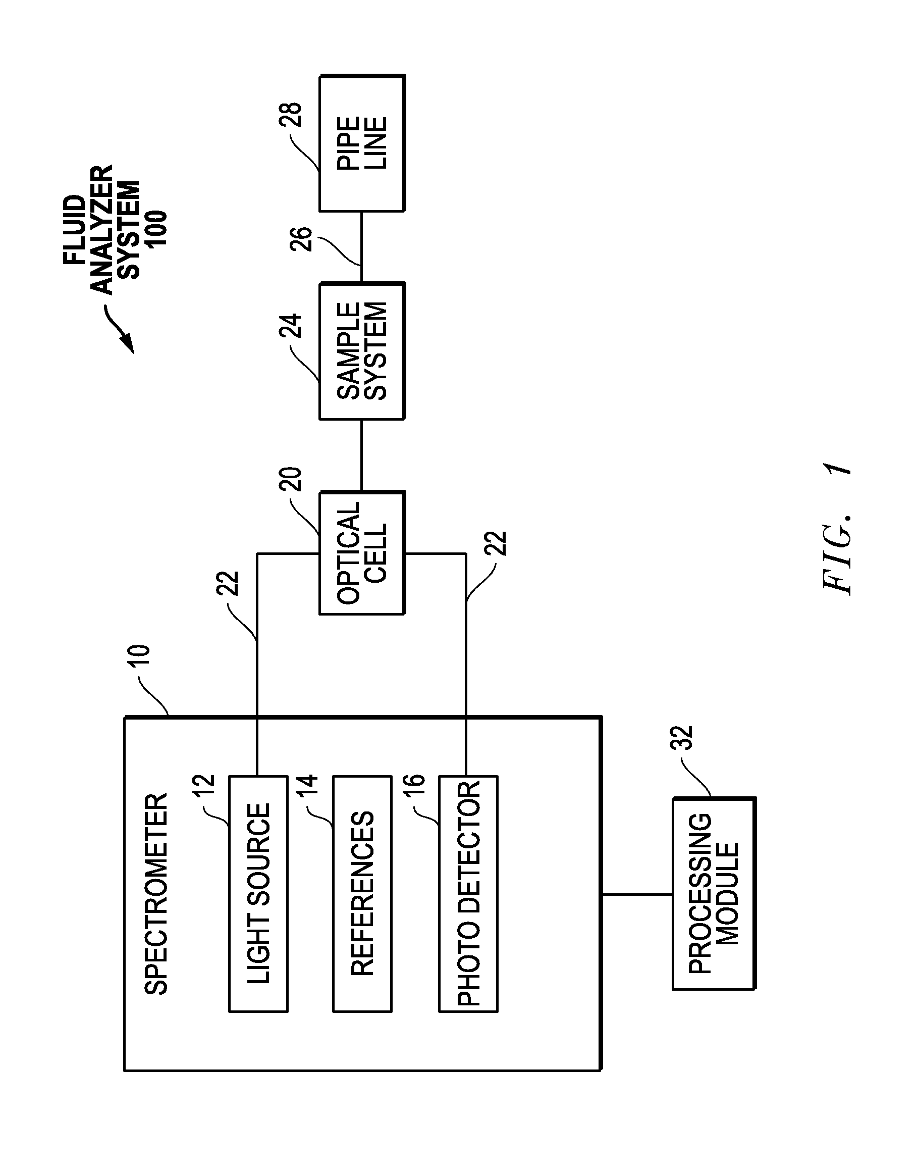
[0019]The present invention is directed to improved methods and systems for, among other things, detecting contaminants in a fluid stream. The configuration and use of the presently preferred embodiments are discussed in detail below. It should be appreciated, however, that the present invention provides many applicable inventive concepts that can be embodied in a wide variety of contexts other than determination of energy content and detection of contaminants in a fluid stream. Accordingly, the specific embodiments discussed are merely illustrative of specific ways to make and use the invention, and do not limit the scope of the invention. In addition, the following terms shall have the associated meaning when used herein:

[0020]“fluid infrastructure” means any infrastructure used in connection with the collection, processing, storage, transmission or distribution of a fluid including, without limitation, if the fluid is a hydrocarbon, any infrastructure between the wellhead and the...


PUM

PropertyMeasurementUnit
wavelength rangeaaaaaaaaaa

Abstract

Methods and systems for real time, in situ monitoring of fluids, and particularly the determination of both the energy content and contaminants in a gas or oil transmission facility, are provided. The system may include two separate scanning sources to scan two different, but overlapping, NIR ranges, or may involve two separate scans from a single scanning spectroscopy source. The first scan ranges from approximately 1550 nm up through 1800 nm and a second scan concurrently scans at a high resolution across a band from approximately 1560-1610 nm, the wavelength of interest for hydrogen sulfide (though similar scans are contemplated in alternative wavelength ranges for alternative contaminants). The second scan may provide very narrow (0.005 nm) step resolution over just the wavelength of interest for the contaminant and may scan at a substantially higher power level. The spectroscopic optical data from the two scans, however obtained, must then be combined into an analytical processing module containing models that analyze the multi-scan data and yield both energy content and contaminant quantitative data.

Description

PRIORITY STATEMENTUnder 35 U.S.C. §119 & 37 C.F.R. §1.78[0001]This non-provisional application claims priority based upon prior U.S. Provisional Patent Application Ser. No. 61 / 702,151 filed Sep. 17, 2012 in the names of Joseph Paul Little, III and Matt Thomas entitled “Trace H2S Detection with Near IR Spectroscopy in Natural Gas Stream Under Pressure Utilizing a Scanning Light Source,” the disclosure of which is incorporated herein in its entirety by reference as if fully set forth herein.BACKGROUND OF THE INVENTION[0002]This invention relates to the real time, in situ monitoring of fluids, and especially to the determination of contaminants in a fluid infrastructure. The invention is directed in particular to the detection of hydrogen sulfide in a natural gas transmission line, but aspects of the invention may be employed to detect other contaminants in other environments as well.[0003]Natural gas is a mixture primarily of methane (CH4) and other hydrocarbons plus carbon dioxide (C...

Claims


Application Information

Patent Timeline
Patent Type & Authority Patents(United States)
IPC IPC(8): G01J3/433G01J5/02G01J3/10G01N21/17G01N21/39G01N21/35
CPCG01N21/39G01J3/433G01N21/61G01J3/108G01N21/359G01N2021/1736G01J3/4338G01J3/28G01N21/3504F17D3/01G01J3/02G01J3/0294G01N21/35G01N21/85G01N33/28G01N2201/06113G05D11/132Y10T137/0335Y10T137/2506
Inventor LITTLE, III, JOSEPH PAULTHOMAS, MATTHEW R.
Owner JP3 MEASUREMENT
Why Eureka
Try Eureka